Continue to Site

Welcome to EDAboard.com

Welcome to our site! EDAboard.com is an international Electronics Discussion Forum focused on EDA software, circuits, schematics, books, theory, papers, asic, pld, 8051, DSP, Network, RF, Analog Design, PCB, Service Manuals... and a whole lot more! To participate you need to register. Registration is free. Click here to register now.

DC/DC flyback converter problem

Status
Not open for further replies.

rera1000

Newbie level 3
Newbie level 3
Joined
Feb 7, 2013
Messages
3
Helped
0
Reputation
0
Reaction score
0
Trophy points
1,281
Activity points
1,301
I have some questions regarding DC/DC flyback converter.

I am doing a project on flyback converter topology.
In my design i am using LT3420 photoflash capacitors to charge high voltage capacitor. In this i am using SMT FLYBACK TRANSFORMER PA0367A .
Actually i am using the same circuit design values as in the datasheet but still am not able to get the output as 320 volts, when i am giving the 5 volts power supply to the circuit, the output is like 3.6 volts and the current is like 350mA after some time the current is suddenly increasing to 2A the IC LT3420 is get burned, and the positive and negative showing shorted .

pls help me regarding this .
 

What is the value of your load and smoothing capacitor?

Even a 320k ohm load, drawing 1 mA, will require several hundred mA from your 5V supply. Can your supply provide that?
Is the resistance low enough through the power loop to permit this?

At startup it will draw a few amperes (if possible). If resistance is too high then the converter may not reach your desired output (320 V).

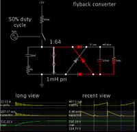
Also in this development stage, I recommend that you try putting a full diode bridge on the secondary. In running simulations I have observed that current will flow during the switch-On cycle at startup, but then it flows during the switch-Off cycle once the capacitor is charged (normal running).

Here is my simulation, with scope traces.


The load has reached 316V. The switch is Off, and the secondary loop is conducting 7 mA. (See rightmost scope traces.)

However it was the opposite at startup. The secondary conducted during switch-On. (See leftmost scope traces.)
 

the load is 100k and the capacitor is 5nF . yes i am giving 5 volts supply which have like 0-3A of current .
actually if u see the datasheet of LT3420 i am useing the same setup as der , the problem is how much current should i supply to the circuit?
 

The primary should draw 600 mA pulses from the supply, or 300 mA average.

You need to confirm whether it is doing that. If current is too low then you cannot hope to get 320V at your load. Your 100k load will draw about 1W of power at 320V.
 

Status
Not open for further replies.

Similar threads

Part and Inventory Search

Welcome to EDABoard.com

Sponsor

Back
Top