rado8705
Newbie level 2

- Joined
- Apr 18, 2014
- Messages
- 2
- Helped
- 0
- Reputation
- 0
- Reaction score
- 0
- Trophy points
- 1
- Activity points
- 19
HI everyone,
I work on my project buck-boost converter with IC LT8705.
Parameters:
Uin = 9 - 30 V DC
Uout = 19 V DC
Iout = 5 A
Scheme:

When I set frequency - fsw = 100 kHz and use inductance L = 10uH, everything work properly at full load 5A in buck region and boost region. This is waveform form switch-node:

and high-side and low-side gate:

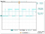
But when I set frequency fsw = 200 khz in buck region, everything is work properly at full load 5A, but when converter work in boost region with load above 1,5 A, it start oscillate like this:

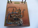
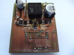
I think, that it is something like sub-harmonic oscillations. I read, that SLOPE compensation prevent these oscillations, but LT8705 has internal slope compensation, so it can´t be set by external resistor. In datasheet is defined the minimal inductance which is given by equation and result is 27uH. I use 32 uH but the problem is not solved. Or is it caused by wrong design of PCB? I have 2 layer pcb. Despite of these oscillatons, on the output is still 19,3 V with full load 5A.


I don´t know where is problem. Thanks for every advice and sorry for my English.
I work on my project buck-boost converter with IC LT8705.
Parameters:
Uin = 9 - 30 V DC
Uout = 19 V DC
Iout = 5 A
Scheme:

When I set frequency - fsw = 100 kHz and use inductance L = 10uH, everything work properly at full load 5A in buck region and boost region. This is waveform form switch-node:

and high-side and low-side gate:

But when I set frequency fsw = 200 khz in buck region, everything is work properly at full load 5A, but when converter work in boost region with load above 1,5 A, it start oscillate like this:

I think, that it is something like sub-harmonic oscillations. I read, that SLOPE compensation prevent these oscillations, but LT8705 has internal slope compensation, so it can´t be set by external resistor. In datasheet is defined the minimal inductance which is given by equation and result is 27uH. I use 32 uH but the problem is not solved. Or is it caused by wrong design of PCB? I have 2 layer pcb. Despite of these oscillatons, on the output is still 19,3 V with full load 5A.


I don´t know where is problem. Thanks for every advice and sorry for my English.
Last edited:
