cerdiablo
Newbie level 4

- Joined
- Jan 20, 2015
- Messages
- 6
- Helped
- 0
- Reputation
- 0
- Reaction score
- 0
- Trophy points
- 1
- Activity points
- 62
Hello, I've just registered on this forums. I hope to learn a lot here. I've coursed a few electronics and electricity subjects on the university, but it's not my specialty, so I would like to increase my knowledge of these fields.
Now I'll present you my doubts.
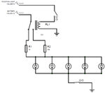
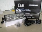
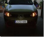
My idea is to design a simple circuit to control the daylights (DRL) of a car. The circuit should do these two things:
The circuit has been modelled with 5 LEDs, but it can change. Also it is important to keep in mind that the values of the resistors are provisional. The greater resistor is supposed to work when the position light is turned on in order to drop more voltage ergo the LEDs drop less voltage.
For me the circuit is correct, but I've seen other versions of similar circuits using a diode bridge and capacitors, so I would like to hear your opinions and suggestions.
Thanks a lot!

Now I'll present you my doubts.
My idea is to design a simple circuit to control the daylights (DRL) of a car. The circuit should do these two things:
- Possibility of disconnecting totally the lights using a switch.
- When position lights are on, the brightness of the LED must decrease.
The circuit has been modelled with 5 LEDs, but it can change. Also it is important to keep in mind that the values of the resistors are provisional. The greater resistor is supposed to work when the position light is turned on in order to drop more voltage ergo the LEDs drop less voltage.
For me the circuit is correct, but I've seen other versions of similar circuits using a diode bridge and capacitors, so I would like to hear your opinions and suggestions.
Thanks a lot!


