cciarleg
Junior Member level 3

- Joined
- Jun 21, 2011
- Messages
- 26
- Helped
- 0
- Reputation
- 0
- Reaction score
- 0
- Trophy points
- 1,281
- Activity points
- 1,544
Hi,
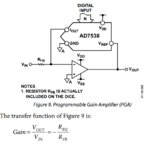
I have a DAC with a built in feedback resistor (the AD7538) and I would like to make a PGA with it (and an op-amp of course). (unipolar-although I would be curious if you could do this with a bipolar output as well)
It is a current output DAC. I'm still learning a lot of this so I have some questions about how to implement the circuit. The attached picture is the recommended PGA config.

I would also like to make sure there is an RC filter on the output of the opamp.
So, I have my analog GND attached to the (+) of my opamp and my opamp output fed back directly to VREF.
Then I get a little confused-I can connect the current output to the (-) of the opamp. But if RFB is my gain resistor, than I also connect that to my (-)? If this is the case than my VREF is the VIN as referred to in the PGA diagram? (which cannot be right)
And to get the RC filter in, I connect the cap from the opamp output to the (-) opamp terminal, and then I'm unsure where to place the resistor since RFB and IOUT are tied together. Is it correct to place it after those lines are tied together?
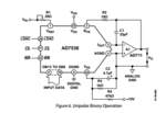
Also, in the unipolar circuit given, they have R2 (10 ohm) placed from VOUT to RFB and I'm not sure what that is for. Is this the 2nd resistor you usually see to set the gain? And do I need it if I have a PGA? Since my VREF is not fixed, I feel like I should have that in there somewhere. If someone could explain briefly the purpose of R2 in the context of

I think that would really help
My last bit of confusion is the voltage to power the opamp. I can either hand it +/-5V or +/-15V. What would be the criteria I would use to determine which one is ideal?
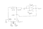
I made a little sketch to help show what I'm confused about and the configuration I currently have it in.

Its a really interesting DAC. I'm just very confused as to how to set it up and how to use the built in resistor. Suggestions and explanations would be much appreciated. Thanks in advance.
I have a DAC with a built in feedback resistor (the AD7538) and I would like to make a PGA with it (and an op-amp of course). (unipolar-although I would be curious if you could do this with a bipolar output as well)
It is a current output DAC. I'm still learning a lot of this so I have some questions about how to implement the circuit. The attached picture is the recommended PGA config.

I would also like to make sure there is an RC filter on the output of the opamp.
So, I have my analog GND attached to the (+) of my opamp and my opamp output fed back directly to VREF.
Then I get a little confused-I can connect the current output to the (-) of the opamp. But if RFB is my gain resistor, than I also connect that to my (-)? If this is the case than my VREF is the VIN as referred to in the PGA diagram? (which cannot be right)
And to get the RC filter in, I connect the cap from the opamp output to the (-) opamp terminal, and then I'm unsure where to place the resistor since RFB and IOUT are tied together. Is it correct to place it after those lines are tied together?
Also, in the unipolar circuit given, they have R2 (10 ohm) placed from VOUT to RFB and I'm not sure what that is for. Is this the 2nd resistor you usually see to set the gain? And do I need it if I have a PGA? Since my VREF is not fixed, I feel like I should have that in there somewhere. If someone could explain briefly the purpose of R2 in the context of

I think that would really help
My last bit of confusion is the voltage to power the opamp. I can either hand it +/-5V or +/-15V. What would be the criteria I would use to determine which one is ideal?
I made a little sketch to help show what I'm confused about and the configuration I currently have it in.

Its a really interesting DAC. I'm just very confused as to how to set it up and how to use the built in resistor. Suggestions and explanations would be much appreciated. Thanks in advance.
