Tizana
Newbie level 6
hi,
I'm using an ARDUINO ZERO and i want to generate an audio signal from the DAC to a small 8Ohm/0.2w onboard speaker like this one **broken link removed**
the ARDUINO ZERO contain an ATSAMD21G18 microcontroller which will read audio .wav file from the SD card and generate audio signal to the DAC. the DAC voltage range is between 0 to 3.3V.
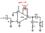
so my amplifier schema is based on this tutorial which uses the LM386 circuit : https://www.arduino.cc/en/Tutorial/SimpleAudioPlayer

i didn't use the 10uF capacitor between the pin 1 and 8 to obtaint a gain of 20 according to the datasheet. note : normally in the tutorial they made a mistake by putting the gain 50 instead of 20 without the capacitor
so my question are :
1/ The DAC output is only a positive voltage between 0 and 3.3V so normally the audio signal from the DAC should be shifted by +1.65V in order to obtain all the + and - wave of the audio signal ? is that right ? see picture bellow :

then normally the DC components should be removed using a capacitor as high pass filter. and according to the tutorial they used a capacitor of 10uF in the output of the DAC which should remove the DC components and in this case the signal will be centered around the 0V.
so my question is how the LM386 will amplify the negative audio signal when the supply of the circuit is between GND and +Vs ? is there something wrong in the circuit ? should i remove the 10uF capacitor and just let the 250uF capacitor in the output of the amplifier remove the DC components? please refer to the picture above.
2/ here's my schema that i modified in order to match with my 0.2w speaker. i want to know if it's OK ?

so the RMS value in the output of the DAC is approximately equal to (3.3V/2)/sqr(2) = 1.166V so i used a voltage divider to reduce it to 0.064V Rms.
Then in the amplifier output the RMS voltage will be 20 x 0.064V = 1.29V
SO approximately the maximum power voltage will be equal to P = U²/Z = (1.29)² / 8 = 0.2W
thx,
I'm using an ARDUINO ZERO and i want to generate an audio signal from the DAC to a small 8Ohm/0.2w onboard speaker like this one **broken link removed**
the ARDUINO ZERO contain an ATSAMD21G18 microcontroller which will read audio .wav file from the SD card and generate audio signal to the DAC. the DAC voltage range is between 0 to 3.3V.
so my amplifier schema is based on this tutorial which uses the LM386 circuit : https://www.arduino.cc/en/Tutorial/SimpleAudioPlayer

i didn't use the 10uF capacitor between the pin 1 and 8 to obtaint a gain of 20 according to the datasheet. note : normally in the tutorial they made a mistake by putting the gain 50 instead of 20 without the capacitor
so my question are :
1/ The DAC output is only a positive voltage between 0 and 3.3V so normally the audio signal from the DAC should be shifted by +1.65V in order to obtain all the + and - wave of the audio signal ? is that right ? see picture bellow :

then normally the DC components should be removed using a capacitor as high pass filter. and according to the tutorial they used a capacitor of 10uF in the output of the DAC which should remove the DC components and in this case the signal will be centered around the 0V.
so my question is how the LM386 will amplify the negative audio signal when the supply of the circuit is between GND and +Vs ? is there something wrong in the circuit ? should i remove the 10uF capacitor and just let the 250uF capacitor in the output of the amplifier remove the DC components? please refer to the picture above.
2/ here's my schema that i modified in order to match with my 0.2w speaker. i want to know if it's OK ?

so the RMS value in the output of the DAC is approximately equal to (3.3V/2)/sqr(2) = 1.166V so i used a voltage divider to reduce it to 0.064V Rms.
Then in the amplifier output the RMS voltage will be 20 x 0.064V = 1.29V
SO approximately the maximum power voltage will be equal to P = U²/Z = (1.29)² / 8 = 0.2W
thx,