greenjames
Newbie level 3

- Joined
- May 30, 2013
- Messages
- 3
- Helped
- 0
- Reputation
- 0
- Reaction score
- 0
- Trophy points
- 1,281
- Activity points
- 1,317
Hello all
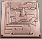
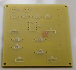
Well I've made (cut) my first board today.
Images will follow tomorrow
Now while I enjoyed my self making this board I did find it very long winded
I drew my design in Diptrace and then exported it to a DXF file which sounds easy How ever when I opened it in my CAD program and VCARVE PRO I was faced with single lines for my traces. Now faced with single lines I just offset them inwards & outwards cool but it took for ever to do also at the end of the day my traces are all a bit close but I think usable but I will let you all be the judge of that. after I offset all the traces I went to my CAD program and added just the holes as on the vcarve drawing I deleted all the holes as I wanted it to be constant which worked very well.
I have to admit my first cut out of the traces was wrong I didn't mirror the drawing o'well you live and learn all in all it worked out quite well but could be a bit faster next time.
I even got cocky and engraved the parts to the top, next time I will spray the top with white paint first and then engrave.
I think I broke two of all my cutters doing this
2 .01 20 deg engraver
2 0.80 end mills
2 2 mm endmill for cutting out the board and Location holes
I think next time I'm going to try and change trace and pad sizes esp on the resistors, diode's,motor,power,LDR also the power amps but for a first go I think I've made a good start
James

