afiqaris
Newbie level 3
i have this problem understanding this circuit from my fellow senior friend in school,.(graduated)
with his permission,im using LTS25np current transducer to monitor load on GUI for my SCADA project.
so i need to create a circuit with this transducer.i used his as reference and a stepping stone.
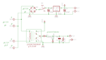
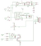
can someone pls help and explain the design output of the transducer. why are there two diodes in parallel and what is the Capacitor and resistor there for?
from what i understand,the inputs to the CT are live of applied load of 1-8A and transformer Vin. And the CT uses 5vcc supplied from the voltage regulator.
PLS help,tqvm.
with his permission,im using LTS25np current transducer to monitor load on GUI for my SCADA project.
so i need to create a circuit with this transducer.i used his as reference and a stepping stone.
can someone pls help and explain the design output of the transducer. why are there two diodes in parallel and what is the Capacitor and resistor there for?
from what i understand,the inputs to the CT are live of applied load of 1-8A and transformer Vin. And the CT uses 5vcc supplied from the voltage regulator.
PLS help,tqvm.