Continue to Site

Welcome to EDAboard.com

Welcome to our site! EDAboard.com is an international Electronics Discussion Forum focused on EDA software, circuits, schematics, books, theory, papers, asic, pld, 8051, DSP, Network, RF, Analog Design, PCB, Service Manuals... and a whole lot more! To participate you need to register. Registration is free. Click here to register now.

Current to voltage converter:- transimpedence amplifier

Status
Not open for further replies.

connect0715207

Newbie level 4
Joined
Jun 30, 2011
Messages
7
Helped
0
Reputation
0
Reaction score
0
Trophy points
1,281
Activity points
1,339
want to design a current to voltage converter, to measure current ranging from 0-100 mA ????
 

Simple method is passing the unknown current value to the known resistor value to calculate the voltage and convert it back to current using the reverse formula to find out the unknown current. Use some precision resistors to find out the value
 

Making the converter in transimpedance amplifier topology is possible, but involves a 100 mA capable amplifier circuit and respective high current consumption from the power supply.

A shunt plus voltage amplifier topology is more appropriate for current ranges above 10 or 20 mA.
 

A transimpedance amp only measures current to ground (it must be in series between the current being measured and ground).
Is that what you want?
Normally a transimpedance amp is used to measure small currents from a signal device, such as a photo-diode, where you want zero voltage drop from the measuring circuit.
What is your application?
 

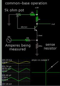
A transistor in common-base operation can do the job.


Bias adjustment is critical. Supply voltage must not change.

With effort you can get near linear response. Output will be close to 0V when you input 0 mA signal.

- - - Updated - - -

Notice that miniscule current is drawn from the power supply. Only a mA or two.
 
Status
Not open for further replies.

Similar threads

Part and Inventory Search

Welcome to EDABoard.com

Sponsor

Back
Top