Continue to Site

Welcome to EDAboard.com

Welcome to our site! EDAboard.com is an international Electronics Discussion Forum focused on EDA software, circuits, schematics, books, theory, papers, asic, pld, 8051, DSP, Network, RF, Analog Design, PCB, Service Manuals... and a whole lot more! To participate you need to register. Registration is free. Click here to register now.

Current sensing using microcontroller

Status
Not open for further replies.

djc

Advanced Member level 1
Joined
Jan 27, 2013
Messages
402
Helped
3
Reputation
6
Reaction score
2
Trophy points
1,298
Location
India
Activity points
4,554
Hi,

Can anybody please tell me that how to sense the current of solar panel using micro controller. I want to use it in MPPT for battery charging. Max current is 1Amp. Please help.
 

Insert a low ohm resistor. Current goes through it, generating a voltage across it. The voltage can be measured.

You do not want the resistor to waste a lot of power, creating a lot of heat. Hence its value should be as low as possible, yet still give a usable reading throughout its intended range of operation.

Example, If you send 1 A through 0.1 ohm, it will give you 100 mV.
 

Thanx bradtherad,

How to charge the battery after sensing the current and voltage?. I thought of using transistor and a mosfet to charge the 14v battery. Is it enough to supply sufficient current or do i have to connect the choke too.
 

how to receive and display in lcd using 8051 instruction
 

resistance used for Current sensing will pass voltage too through it. So when voltage of panel is maximum above 5v, it will destroy the controller. Also current direction through current sense resistor will be different while charging and discharging. So how to sense that current direction.

For LCD, collect the values, write LCD display routine and display on LCD. Look for LCD datasheet for pin configuration , 4 bit or 8 bit data configuration of LCD.
 

resistance used for Current sensing will pass voltage too through it. So when voltage of panel is maximum above 5v, it will destroy the controller. Also current direction through current sense resistor will be different while charging and discharging. So how to sense that current direction.


No, as Brad said its the voltage developed across the resistance, not the voltage from the solar panel or battery.
Its typically very small, as said about 100mv, for use with a micro its often fed into an op amp to boost the voltage to a level more suitable for the micro; trying to get clear readings from a 0 to 100nv signal is not easy as say from a x20 boost to 2v.

As for the 'direction' of the current flow, if you just use one current sense resistor at the junction of the battery how will you know what the true charging or load currents are ? you really need to monitor with 2 resistors, one in the charging line and one on the load line.

You might find using these little ebay volt/amp meters a simpler option, got some the other day, seem quiet accurate.
They have inbuilt shunts so no need for any external resistors.
**broken link removed**

Here is a simple looking MPPT charger, but no idea if it is a good project; though you could always start with a simpler Lm317 charger.
https://www.electroschematics.com/9718/solar-boost-converter-mppt-charge-controller/

https://www.insidegadgets.com/2012/06/25/simple-lm317-solar-charger-for-12v-batteries/
 

Use a series resistance of low value and take voltage across it ( < 200 mV). Amplify it to 5V using an OpAmp and feed the output of OpAmp to adc of MCU. 5V will represent 200 mV. If 1A is represented by 100 mA then 2.5V adc input represents 1A.
 

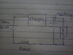
I was thinking of keeping solar panel and battery in parallel with controller section in between them. SO that while charging current will flow through the battery,resistor clockwise and while discharging through the battery to the load. That's why i asked what will be the current through the resistance and its direction when battery is discharging. Is any other way than using an op amp.
 

INA139 from TI is a current shunt monitor, and you get the current expressed in a voltage output.
 
I had a backup power system years ago. I wanted to arrange things so I could put a single current meter on the battery, bidirectional. An op amp would make this possible.

When I thought about it, however, I realized that current going out of the battery would be much greater than current going in. I would need two different scales, and two different gains.

I decided I could not do it with one meter. I would need two.
 

Hi,

If you see the datasheet , figure 5 of the little chip INA139 that Gorgon mentioned it looks like what you are after, a bi direction current monitor.
 

2014-03-28 16.52.18.jpg
This is how i want to do it.

- - - Updated - - -

And one more thing, how to charge the battery if i am correct i have to use transistor & mosfet from controller. DO i need to use choke also.
 

Would any body guide me if my approach is correct or not? Do i have to use choke also for charging the battery with transistor and mosfet.
 

Your general concept is correct. It will need more wires and components, to make it into a working schematic.

A choke (inductor) is not essential for charging a battery from a PV panel. However there will be an inductor in your charge controller if it is a buck converter.
 

Status
Not open for further replies.

Similar threads

Part and Inventory Search

Welcome to EDABoard.com

Sponsor

Back
Top