phenol
Junior Member level 1
Hi
I'm building a 12-440V/500W push-pull converter based on the UC2825A pwm controller.
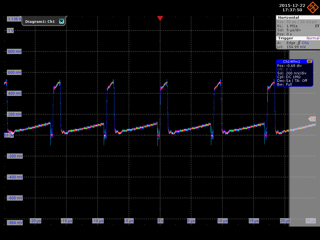
The current sense xfrm (toroid)is now placed over the common junction of the two primaries, thus receiving unipolar pulses. The max duty cycle is ~93% so it has very short time to reset and fails to do so at heavy loads--the sensed current assumes negative slope. If i slide on a bigger core it works, but the reset pulses wildly exceed -500V. Even though they are about 300ns each, I don't feel comfortable running them close to other sensitive lines.
Plus, if i clamp the leakage inductance voltage spikes seen across the mosfets instead of allowing avalanche breakdown or even higher voltage spikes below the breakdown point, even the bigger core starts to act up. It appears that those overshoots help reset the current xfrm.
Now the question-- i need some ideas how to avoid saturation and a different placement of the xfrm where bipolar current can be sensed. I know i can pass the 'outer' legs of the power transformer thru the same current sense toroid in an antiparallel fashion, but it then becomes very convoluted as the primaries use 10 strands of wire each.
Maybe use two cores-one per leg- and then parallel them somehow...?
I'm building a 12-440V/500W push-pull converter based on the UC2825A pwm controller.
The current sense xfrm (toroid)is now placed over the common junction of the two primaries, thus receiving unipolar pulses. The max duty cycle is ~93% so it has very short time to reset and fails to do so at heavy loads--the sensed current assumes negative slope. If i slide on a bigger core it works, but the reset pulses wildly exceed -500V. Even though they are about 300ns each, I don't feel comfortable running them close to other sensitive lines.
Plus, if i clamp the leakage inductance voltage spikes seen across the mosfets instead of allowing avalanche breakdown or even higher voltage spikes below the breakdown point, even the bigger core starts to act up. It appears that those overshoots help reset the current xfrm.
Now the question-- i need some ideas how to avoid saturation and a different placement of the xfrm where bipolar current can be sensed. I know i can pass the 'outer' legs of the power transformer thru the same current sense toroid in an antiparallel fashion, but it then becomes very convoluted as the primaries use 10 strands of wire each.
Maybe use two cores-one per leg- and then parallel them somehow...?