radioactive1014
Newbie level 2
Hi,
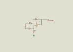
I am designing a circuit for my University project which involved measuring the current drawn by the load. I am using LT1495 rail to rail opamp. I have attached the circuit here. It's a simple differential amplifier with 4 resistors. Circuit works fine when the current is higher than .34 A. Whenever the current goes below .34 it can't sense anymore ( the output remains .34 ).

I would appreciate if anyone can help me solving the problem. Another thing is as I am on deadline I already ordered the PCB (it was very stupid of me ). so I can't change the circuit but all I can do is to change the value of the resistors. Is it possible to make it work?
Thanks for your help in advance.
I am designing a circuit for my University project which involved measuring the current drawn by the load. I am using LT1495 rail to rail opamp. I have attached the circuit here. It's a simple differential amplifier with 4 resistors. Circuit works fine when the current is higher than .34 A. Whenever the current goes below .34 it can't sense anymore ( the output remains .34 ).

I would appreciate if anyone can help me solving the problem. Another thing is as I am on deadline I already ordered the PCB (it was very stupid of me ). so I can't change the circuit but all I can do is to change the value of the resistors. Is it possible to make it work?
Thanks for your help in advance.