tom_hanks
Full Member level 5
Hi there,
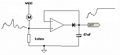
Can any one suggest a technique to detect the current peak consumption. my system is running a motor on the interval of 100ms.
in every cycle, motor consume some current, i want to find out the maximum value of the current in one cycle.
or other way is to calculate the avg of current in one cycle...
what do u think is appropriate?
any circuit ?
depends upon answer i am ready to donate the points
")