florescent
Member level 1
- Joined
- Mar 9, 2009
- Messages
- 41
- Helped
- 3
- Reputation
- 6
- Reaction score
- 3
- Trophy points
- 1,288
- Location
- The Lone Star, Texas
- Activity points
- 1,677
Dear All
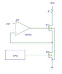
I am designing a stimulator that can inject a steady 5mA. To be independent on the load impedance, a current mode stimulator has been chosen for my design. I have researched and designed five different circuits, and the attached one is the best in results so far.
In my application, the load impedance (at this moment, resistance only) can be varied upto 1kohm. The 5mA current should be steady under this load variation.
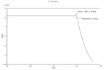
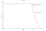
The results from this circuit attached also. The trade-off, as you can see, is the amplitude of the current vs load resistance. I can't set the circuit that provides around 5mA with upto 1kohm.
The second concern is that I prefer to have such a circuit whose load resistance is at the ground, not on the VDD. In this way, I don't need to have a virtual ground.
I would really appreciate for your comments or suggestions on other circuits.
Thank you for reading
I am designing a stimulator that can inject a steady 5mA. To be independent on the load impedance, a current mode stimulator has been chosen for my design. I have researched and designed five different circuits, and the attached one is the best in results so far.
In my application, the load impedance (at this moment, resistance only) can be varied upto 1kohm. The 5mA current should be steady under this load variation.
The results from this circuit attached also. The trade-off, as you can see, is the amplitude of the current vs load resistance. I can't set the circuit that provides around 5mA with upto 1kohm.
The second concern is that I prefer to have such a circuit whose load resistance is at the ground, not on the VDD. In this way, I don't need to have a virtual ground.
I would really appreciate for your comments or suggestions on other circuits.
Thank you for reading