mtwieg
Advanced Member level 6
Hello, I've taken on a project in which I have to control the voltage applied to a brushed DC motor, output 10-16V (unidirectional) and 5-15A. Vin can range from 10-24V, so I need a topology capable of having Vout greater than or equal to Vin (though the polarity of Vout can be negative, that's not a problem). Also I have major restrictions on power dissipation; this supply is to be housed in a sealed plastic enclosure (not my call), about 50 cubic inches. At first I was planning on making a fixed output DC-DC to give 24V or so out, then using a DC chopper to drive the motor, but I'm doubting whether such a two stage approach can give low enough losses.
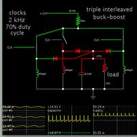
Using a single variable output DC-DC stage seems like it would have better efficiency, but buckboost converters have very high output ripple currents, so I would need huge capacitors. What I keep coming back to it the Cuk topology, which advertises low ripple currents on input and output, but I have no experience designing or using one. In particular I'm wondering if the size of blocking capacitor will be huge in itself... Does anyone with experience in this topology have any thoughts on its merits for this application?
Using a single variable output DC-DC stage seems like it would have better efficiency, but buckboost converters have very high output ripple currents, so I would need huge capacitors. What I keep coming back to it the Cuk topology, which advertises low ripple currents on input and output, but I have no experience designing or using one. In particular I'm wondering if the size of blocking capacitor will be huge in itself... Does anyone with experience in this topology have any thoughts on its merits for this application?
