Continue to Site

Welcome to EDAboard.com

Welcome to our site! EDAboard.com is an international Electronics Discussion Forum focused on EDA software, circuits, schematics, books, theory, papers, asic, pld, 8051, DSP, Network, RF, Analog Design, PCB, Service Manuals... and a whole lot more! To participate you need to register. Registration is free. Click here to register now.

CT60AM-18F with IR2110 circuits

Status
Not open for further replies.

madhurasugandhi

Newbie level 4
Joined
Aug 22, 2009
Messages
5
Helped
0
Reputation
0
Reaction score
0
Trophy points
1,281
Activity points
1,309
inverter using sg3524

i want to design an inverter using sg324 but im not understanding where shld i give 230v 50hz input to the ic (at which pin) or shld it be converted to dc and then given
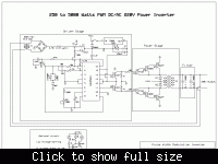
 

sg3524 sine wave inverter

Hi Madurasugandhi,
I dont mean to be rude here but you dont seem to have
a clue about the power electronics. If you think you can stick 230v 50hz into a sg3524 ic, i am afraid you should stay away from from HV stuff. you could hurt or kill yourself, son.
 

using sg3524

for generating a pwm wave u need a carrier and a modulating s/g right .. carrier is generated according to rt and ct where is the modulating s/g.. please help
 

inverter using ic 3524

I think I understand what you intend to do: Making a simple sine wave inverter, using a 50Hz power transformer, dirven in push pull or with a bridge, and pulse-width-modulating the driving transistors to create the sine wave. That was commonly done in "ancient" times, but nowadays it's not done much, because such an inverter is heavy, and the loss at zero or low load is rather high.

Anyway, to modulate a sine wave function with a 3524, you can put the sine wave into the COMP pin, which will override the error amplifers. If you put in a sine wave that swings between roughly 1 and 4V (the exact levels need to be adjustable), then the output pulse width will be modulated from zero for the negative peak of the sine, to half length for the zero crossing of the sine, to full pulse length for the positive peak of the sine.

The problem is that this is NOT what you need to drive such an inverter's power circuit! For a push pull, you need instead a drive circuit that modulates one output from zero to full pulse length and back, modulating one HALF wave of the sine wave, while keeping the other transistor off, and then does the same again, but on the second transistor, keeping the first one off! The 3524 cannot do that. Maybe there is an IC that can do this, but I don't know it. I have seen such inverters implemented with more discrete circuitry, or with a microcontroller.
 

application using sg3524

in this ckt what will be the frequency of op ac s/g


Status
Not open for further replies.

Similar threads

Part and Inventory Search

Welcome to EDABoard.com

Sponsor

Back
Top