Continue to Site

Welcome to EDAboard.com

Welcome to our site! EDAboard.com is an international Electronics Discussion Forum focused on EDA software, circuits, schematics, books, theory, papers, asic, pld, 8051, DSP, Network, RF, Analog Design, PCB, Service Manuals... and a whole lot more! To participate you need to register. Registration is free. Click here to register now.

Crt transformer question

Status
Not open for further replies.
J

Javid.zare.s

Guest
Hi there
My crt's high voltage transformer's coil is broken from top(one of coils ,i glued it :| )
My Question is
---should i find another coil or its ok? (Monitor starts slow but it does anyway)
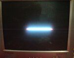
--Why i see only a single horizontal line (it had this issue before breaking coil)

Thax guys
 

Buy a new transformer.

But BE CAREFUL! You can kill yourself messing around with that high voltage. SERIOUSLY. If you have any doubts, don't do it.
 

    V

    Points: 2
    Helpful Answer Positive Rating
Apparently the vertical deflection circuit is defective too. The transformer has nothing to do with vertical deflection.
 

    V

    Points: 2
    Helpful Answer Positive Rating
Buy a new transformer.

But BE CAREFUL! You can kill yourself messing around with that high voltage. SERIOUSLY. If you have any doubts, don't do it.
I can't find tramsformers any more, no one is selling them and are expensive az a new crt
 

Apparently the vertical deflection circuit is defective too. The transformer has nothing to do with vertical deflection.

Hmmmm ,ok .so i should fix vertical iic , maybe i should resolder it
 

Hmmmm ,ok .so i should fix vertical iic , maybe i should resolder it

If the vertical deflection is not seem, please test the last point first, whether you see any voltage at the CRT end. If you can see the horizontal line, the high voltage is perhaps fine.
 

    V

    Points: 2
    Helpful Answer Positive Rating
If the vertical deflection is not seem, please test the last point first, whether you see any voltage at the CRT end. If you can see the horizontal line, the high voltage is perhaps fine.

Yeah i can see the horizontal line , it flashes every 5 second I'm not sure it flash before...
Any ways it didn't fix by resoldering:roll:
my monitor model is samsung syncmaster s1756 (753s) and im not sure which ic is vertical ic :/ i fix it by hitting monitor ,this method is no longer working;-)
 

First, if a piece of the ferrite core of the HV transformer broke and that's what you glued, then it should be ok. The core helps tune the transformer and having it physically together usually accomplishes the tuning. The vertical output IC is usually an inline IC (all pins in a single row) of maybe 12 or 14 legs attached to a heatsink. If it works when flexing the board, then look on the solder side of the board for solder cracks on the legs of that IC which will be round jagged holes or a ***** in the circuit foils which also occur around heavily weighted areas like heatsinks. If you attach good close up photos of the circuit side, I can help you look. Cameras now have amazing detail and can sometimes spot trouble the eye can't see. Also with the component side, I can help identify the vertical IC.
 

    V

    Points: 2
    Helpful Answer Positive Rating
First, if a piece of the ferrite core of the HV transformer broke and that's what you glued, then it should be ok. The core helps tune the transformer and having it physically together usually accomplishes the tuning. The vertical output IC is usually an inline IC (all pins in a single row) of maybe 12 or 14 legs attached to a heatsink. If it works when flexing the board, then look on the solder side of the board for solder cracks on the legs of that IC which will be round jagged holes or a ***** in the circuit foils which also occur around heavily weighted areas like heatsinks. If you attach good close up photos of the circuit side, I can help you look. Cameras now have amazing detail and can sometimes spot trouble the eye can't see. Also with the component side, I can help identify the vertical IC.

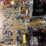
Oh god thanks man i owe you, this is how monitor screen looks like( should show a message "no signal" but shows just a line)
image.jpeg
Top view
image.jpeg
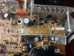
Close up to vertical ic (as u said it does have about 11 legs and heat sink)(ic :KA2142 or KA2442 cant see exact number)
image.jpeg
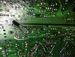
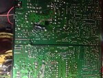
And down of it:
image.jpeg
image.jpeg
u can see I soldered and wired sth in the right side,its a transistor which burned when i hit the monitor to bring it back to life , after replacing transistor I couldn't see the picture like before also hitting doesn't bring it to normal...(transistor d2058-->low power amplifier )
 

Wait a minute. You HIT your monitor and that made a transistor burn up? I think there's a lot more going on here than you're telling us.
 

    V

    Points: 2
    Helpful Answer Positive Rating
It appears you now have two problems. Since the width of the line doesn't fill the entire screen, you have a problem in the horizontal deflection as well as no vertical deflection. I'm sorry to say, your board looks pretty scary with all the pulled foils and wire patches. If the damage to the flyback transformer was bad enough, it could cause insufficient width. Was the line all the way across the screen before the transistor failed but after you did the glue repair? Double check your circuit paths where you soldered and jumpered. Also clean out any flux bridges between foils with alcohol and a toothbrush. Flux removal spray is the best. KA2142 is a vertical deflection IC. Do you have a voltage meter? At this point you will need one. Pin 2 is the voltage supply. It should have like somewhere around 12 volts. Also do not leave it powered on more than a minute in this condition. It will burn a line in the screen and probably the transistor you replaced is running hot and will fail. Turn the brightness down to protect the tube.

Hmmm the "no singal " message on crt is a sort of box message that should not fill all the screen so horizontal ic is ok( the message goes to right and left) (the picture width is same az before)
About not leaving it on..... Actually i did...for several hours:/
So at this point i should test the ic, i have a multimeter but never used it to test an ic... Ill give it a try, isn't pcb dangerous for high voltage when on?

It appears you now have two problems. Since the width of the line doesn't fill the entire screen, you have a problem in the horizontal deflection as well as no vertical deflection. I'm sorry to say, your board looks pretty scary with all the pulled foils and wire patches. If the damage to the flyback transformer was bad enough, it could cause insufficient width. Was the line all the way across the screen before the transistor failed but after you did the glue repair? Double check your circuit paths where you soldered and jumpered. Also clean out any flux bridges between foils with alcohol and a toothbrush. Flux removal spray is the best. KA2142 is a vertical deflection IC. Do you have a voltage meter? At this point you will need one. Pin 2 is the voltage supply. It should have like somewhere around 12 volts. Also do not leave it powered on more than a minute in this condition. It will burn a line in the screen and probably the transistor you replaced is running hot and will fail. Turn the brightness down to protect the tube.

Sir I've tested the voltage btw pin 2 and 10 the voltage was 7-8 volts
And btw pin 2 and 5 the voltage was 16 volts.
Datasheet for ic;
https://www.quartz1.com/price/PIC/410N0317000.pdf
When i fliped the monitor faced down it didn't turn on , is that a hint?(tried to turn on but it could not)
 

Sometimes you just have to call it a day and give up. CRT based equipment is becoming hard to fix now that LCD has taken over almost everywhere so the supply of parts is drying up and the expertise to fault find to component level is slowly drifting away as engineers move towards retirement.

I've seen equipment I spent weeks developing, prototyping and putting in production being advertized on Ebay for almost nothing, heart breaking but you have to let go sometimes.

Brian.
 

I've seen equipment I spent weeks developing, prototyping and putting in production being advertized on Ebay for almost nothing, heart breaking but you have to let go sometimes.

Sad but true. I have seen tube (valve) based color TVs that needed a crane to move but I appreciated the technology and its progress. Both Japanese and Korean manufacturers are repair-unfriendly and if you cannot find the fault, it is certainly not your fault. It is in the design.

I still remember the wonderful service manuals Tektronix and HP produced (the good old days) but today it is nothing but a battle of wits...
 

Status
Not open for further replies.

Similar threads

Part and Inventory Search

Welcome to EDABoard.com

Sponsor

Back
Top