Continue to Site

Welcome to EDAboard.com

Welcome to our site! EDAboard.com is an international Electronics Discussion Forum focused on EDA software, circuits, schematics, books, theory, papers, asic, pld, 8051, DSP, Network, RF, Analog Design, PCB, Service Manuals... and a whole lot more! To participate you need to register. Registration is free. Click here to register now.

Coupled inverting Cuk looks too good to be true?

Status
Not open for further replies.

cupoftea

Advanced Member level 5
Joined
Jun 13, 2021
Messages
2,660
Helped
54
Reputation
108
Reaction score
116
Trophy points
63
Activity points
13,985
Hi ,
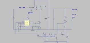
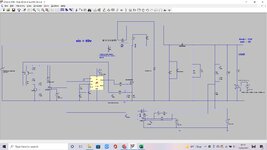
The attached coupled inverting Cuk gives -15V 2A from 60Vin.

It looks great because the coupling can be poor and widely variant and it makes little difference......also, there is no clamp overvoltage like you get in a flyback....no overvoltage ringing on the diode.
So whats wrong with it?
Why is it very little used?

I must admit theres a risk of the opamp input getting -0.7v on it....so would need an opamp tolerant of that.
 

Attachments

  • Cuk 60vin minus15V 2A out.zip
    2.1 KB · Views: 98
  • cuk.jpg
    cuk.jpg
    107.8 KB · Views: 106

aah..well the diode D5 is needed , otherwise the vout goes positive at startup due to ringing between the leakage of the coupled inductor and the series capacitor.
Any more woes?
 

Attachments

  • cuk _1.jpg
    cuk _1.jpg
    204.8 KB · Views: 102
  • Cuk 60vin minus15V 2A out _1.zip
    2.8 KB · Views: 93

Place a diode across C18 to limit pos excursion to ~ 0.7 V

Coupled Cuk's suffer from lack of design input from designers - too much coupling requires a very stiff voltage source - else the cap at the input contributes to a resonance effect ( you can see this already on the sim ) - you have the ultimate voltage source in your sim - the 100nF cap is redundant for sim purposes ..

They are hard to stabilise in CCM - as you may discover with real world parts and sources...

Theoretically a properly coupled L leads to an halving of ripple current on both sides - compared to uncoupled - this is easy to verify on sim.

update: have copied your sim and varied quite a bit for control loop, load, and Zsource, and power components - for that controller it is surprisingly stable ( in LT spice ) will be interested to read later if it is in the real world also ...
 
Last edited:
Thanks, i suspect the coupled Cuk is a bit similar to the coupled SEPIC?. With the coupled SEPIC, i remember that the resonance T of L(leak) and C(series) had to be >T(sw), otherwise there would be unwanted ringing inside the switching period, which would add to core loss.

Also, i remember it being much easier to control when Duty <0.5.
Also, as you kindly say, DCM easier to control than CCM.

I may experiment with adding some stray R/L downstream of the stiff voltage source, then a capacitor, to make v(source) look less stiff......and also seeing the effect of adding an extra external "leakage" inductor in series with the primary.......since as you kindly say, too much coupling can possibly result in malaise here......i am not sure what coupling i would get if i just wind a primary layer over a secondary layer? (no interleaving).....(this is one of the benefits seen compared to using a flyback...no interleaving needed...).

..this is for what i term a "dirty" converter...one that is all PTH components because it lives on a bendy >1kW SMPS main board, and we cant afford to make up an SMD daughter board for the control of this coupled Cuk.......so will run at low frequency, and will damp fairly heavily the switching transitions.....so the "ugly" PTH CS pin filter doesnt have to be too good.
 
Last edited:

Interestingly the attached sepic (LTspice) switches at 35kHz, and is in DCM, 60vin and 24vout and 1A out.
If the "external" leakage inductor and sepic cap have a resonance frequency of 35khz, AND the SEPIC cap is 4.7uF......then the input current has overly high pkpk value

..however...

...if the Sepic cap is 10uF, and the "external" leakage inductor is 2.07uH, then again thats got a resonant frequency equal to the f(sw) at 35khz.....but it does NOT have the overly high pkpk input current this time.

.....So it seems that a higher value sepic cap, (with a lower ripple voltage on it)...is much less likely to suffer the high pkpk input current.

i'd postulate, as a guide, that the ripple voltage on the SEPIC cap is best if its less than 5% of vin for the sepic......so eg make the sepic cap high enough uF for that.

This situation of input current ringing wildly high when the L(leak) and C(series) resonant frequency is at the switching frequency, is much worse when there are big input and output capacitors.....and occurs in the Cuk aswell.
 

Attachments

  • SEPIC 60vin PLUS 24V 1A out _35khz.zip
    2.5 KB · Views: 87
Last edited:

...In fact, when you get L(leak)/C(series) resonant frequency on f(sw), its an impressive sine wave generator.......got 13Apkpk input sine current whereas less than 1.2Apk when not at resonance.
 

Might have to do with personalities, Dr. Cuk can be abrasive
and dogmatic and dismissive of dumb user questions as he
promotes his various topologies. Therefore there's a lot less
third party material that's good for unfamiliarized folks to study,
and a lot less "on the shelf" controllers to choose than more
"classic" architectures. Would be good if you found a friendlier
"guru" than the man on the mountaintop, to start the journey.
 
One of the issues with the older original Cuk circuits is that the dynamic response is really poor ( unless in DCM )

unsurprisingly the newer resonant Cuk topologies also have issues relating to dynamics and load stepping - which when put to Prof Cuk rarely get a response - 3 guesses why this is ....
 
Status
Not open for further replies.

Similar threads

Part and Inventory Search

Welcome to EDABoard.com

Sponsor

Back
Top