kayaoo
Member level 5
- Joined
- Sep 2, 2003
- Messages
- 80
- Helped
- 20
- Reputation
- 40
- Reaction score
- 17
- Trophy points
- 1,288
- Location
- Shanghai, China
- Activity points
- 595
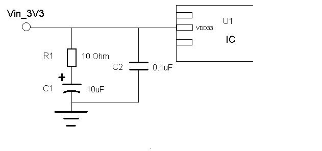
I found a RF IC sample board has the following VDD bypass network: a 10Ohm resistor is added in serial to the big bypass capacitor. What is the benefit of the 10ohm resistor( R1)?:-?