Continue to Site

Welcome to EDAboard.com

Welcome to our site! EDAboard.com is an international Electronics Discussion Forum focused on EDA software, circuits, schematics, books, theory, papers, asic, pld, 8051, DSP, Network, RF, Analog Design, PCB, Service Manuals... and a whole lot more! To participate you need to register. Registration is free. Click here to register now.

[SOLVED] correct fuse settings for 18F4550 as an USB device

Status
Not open for further replies.

varunme

Advanced Member level 3
Joined
Aug 10, 2011
Messages
741
Helped
17
Reputation
36
Reaction score
17
Trophy points
1,318
Activity points
5,764
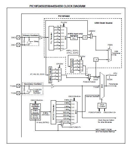
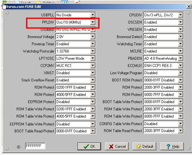
I am having trouble in using 18F4550 as USB device ( I tried all the firmwares from microchip ) , I think its because of the faulty fuse settings in the burner (Microburn) , someone kindly review the setting and advice me a good setting

untitledp.jpg

thanks
varun
 
Last edited:

Somehow, your picture cannot be enlarge

---------- Post added at 11:25 ---------- Previous post was at 11:25 ----------

Anyway, these are the settings using hitechC:

Code:
// PIC18F4550/PIC18F2550 fuse configuration:
// Config word 1 (Oscillator configuration)
// 20Mhz crystal input scaled to 48Mhz and configured for USB operation
__CONFIG(1, USBPLL & IESODIS & FCMDIS & HSPLL & CPUDIV1 & PLLDIV5);
// Config word 2
__CONFIG(2, VREGEN & PWRTDIS & BOREN & BORV20 & WDTDIS & WDTPS32K);
// Config word 3
__CONFIG(3, PBDIGITAL & LPT1DIS & MCLREN);
// Config word 4
__CONFIG(4, XINSTDIS & STVREN & LVPDIS & ICPORTDIS & DEBUGDIS);
// Config word 5, 6 and 7 (protection configuration)
__CONFIG(5, UNPROTECT);
__CONFIG(6, UNPROTECT);
__CONFIG(7, UNPROTECT);
 
  • Like
Reactions: varunme

    varunme

    Points: 2
    Helpful Answer Positive Rating
Hi , john blue these are setting for 18F4550 for using as USB ?
 

Now the picture can be enlarged
 

its 20MHz crystal
 

Here are the fuses available in microburn for 18F4550 , can someone suggest the approriate fuses for 18F4550 as usb device ?

Code:
USBPLL			/by2
				No divide

Oscillator			HS OSC w/pll HS used by USB
				HS OSC  HS used by USB
				Intrn OSC  HS used by USB
				Intrn OSC  XT used by USB

Brown Out Voltage	2V
				2.7V
				4.2V
				4.5V


Powerup timer            En
                                Dis


WDT postscale		1:32768
				1:16384
				1:8192
				1:4096
				1:2048
				1:1024
				1:512
				1:256
				..
				..
				..
				..
				1:1

LPT1 OSC			Low Power  mode
				High Power mode

CCP2MX 			MUC RC1
				MUC RE7/RB3

XINST			Dis
				En

Stalk Overflow		En 
				Dis
	
Rom Protect		0200-1FFFF Dis
				0200-1FFFF EN

Rom Protect		4000-5FFFF Dis
				4000-5FFFF EN

EEprom prot		En
				Dis

Rom table write prot	En
				Dis

EEprom table write protEn
				Dis

Boot table read Prot	0000-1FFF Dis
				0000-1FFF En


CPUDIV			Div/6 wPLL Div/4
				Div/4 wPLL Div/3
				Div/3 wPLL Div/2
				Div/2 wPLL No div


OSCSEN			En 
				Dis

VREGEN			En
				Dis

Brownout Detect		En
				Dis


WDT				En
				Dis

MCLR				En
				Dis
	
PBADEN			AD 4:0 Reset=analog
				AD 4:0 Reset=digital


ECCMUX			ENH CCP1 RE6 3
				ENH CCP1 RH7 4

Low voltage program	Dis
				En


Boot rom detect 		0000-01FFF Dis
				0000-01FFF EN
	
rom protect 		2000-3FFFF Dis
				2000-3FFFF EN
	

rom protect 		6000-7FFFF Dis
				6000-7FFFF EN


Boot table write prot	0000-3FFFF Dis
				0000-3FFFF En


Rom table write prot	2000-3FFFF Dis
				2000-3FFFF EN


Rom table write prot	6000-1FFFF Dis
				6000-1FFFF EN


config table write prot	Dis
				En


Rom Table read prot	2000-3FFF Dis
				2000-3FFF En
 

Your PPLDIV is wrong. The one you are using is 40MHz crystal.
 

The fuses i used is marked in star

Code:
Fuse				Available option		 


USBPLL			/by2*
				No divide

Oscillator			HS OSC w/pll HS used by USB*
				HS OSC  HS used by USB
				Intrn OSC  HS used by USB
				Intrn OSC  XT used by USB

Brown Out Voltage	2V*
				2.7V
				4.2V
				4.5V


Powerup timer          En*
                               Dis


WDT postscale		1:32768	*
				1:16384
				1:8192
				1:4096
				1:2048
				1:1024
				1:512
				1:256
				..
				..
				..
				..
				1:1

LPT1 OSC			Low Power  mode*
				High Power mode

CCP2MX 			MUC RC1*
				MUC RE7/RB3

XINST			Dis*
				En

Stalk Overflow		En*
				Dis
	
Rom Protect		0200-1FFFF Dis
				0200-1FFFF EN*

Rom Protect		4000-5FFFF Dis*
				4000-5FFFF EN

EEprom prot		En
				Dis*

Rom table write prot	En
				Dis*

EEprom table write prot    En
				      Dis*

Boot table read Prot	0000-1FFF Dis*
				0000-1FFF En


CPUDIV			Div/6 wPLL Div/4*
				Div/4 wPLL Div/3
				Div/3 wPLL Div/2
				Div/2 wPLL No div


OSCSEN			En 
				Dis*

VREGEN			En
				Dis*

Brownout Detect		En
				Dis*


WDT				En
				Dis*

MCLR			En*
				Dis
	
PBADEN			AD 4:0 Reset=analog*
				AD 4:0 Reset=digital


ECCMUX			ENH CCP1 RE6 3*
				ENH CCP1 RH7 4

Low voltage program	Dis*
				En


Boot rom detect 		0000-01FFF Dis*
				0000-01FFF EN
	
rom protect 		2000-3FFFF Dis*
				2000-3FFFF EN
	

rom protect 		6000-7FFFF Dis*
				6000-7FFFF EN


Boot table write prot	0000-3FFFF Dis*
				0000-3FFFF En


Rom table write prot	2000-3FFFF Dis*
				2000-3FFFF EN


Rom table write prot	6000-1FFFF Dis*
				6000-1FFFF EN


config table write prot	Dis*
				En


Rom Table read prot	2000-3FFF Dis*
				2000-3FFF En


Please change your PPLDIV to the one for 20MHz first. The one you are using now is for 40MHz
 
  • Like
Reactions: varunme

    varunme

    Points: 2
    Helpful Answer Positive Rating
hi john blue
how should i rewrite to correct the fuse ?

---------- Post added at 06:36 ---------- Previous post was at 06:35 ----------

Div/2 wPLL No div ?


---------- Post added at 14:46 ---------- Previous post was at 14:44 ----------

PLL divide by 5
 

yes , that was corrected , it was a screen shot before correction , can u correct the typed version of the post ?
 

Have you tested after correction? :)
 

my real doubts are


CPUDIV Div/6 wPLL Div/4*
Div/4 wPLL Div/3
Div/3 wPLL Div/2
Div/2 wPLL No div


USBPLL /by2*
No divide


Oscillator HS OSC w/pll HS used by USB*
HS OSC HS used by USB
Intrn OSC HS used by USB
Intrn OSC XT used by USB

---------- Post added at 07:08 ---------- Previous post was at 07:08 ----------

Have you tested after correction? :)
yes , i have checked
 

my real doubts are


CPUDIV Div/6 wPLL Div/4*
Div/4 wPLL Div/3
Div/3 wPLL Div/2
Div/2 wPLL No div


USBPLL /by2*
No divide


Oscillator HS OSC w/pll HS used by USB*
HS OSC HS used by USB
Intrn OSC HS used by USB
Intrn OSC XT used by USB

---------- Post added at 07:08 ---------- Previous post was at 07:08 ----------


yes , i have checked


CPUDIV determines the program oscillator clock. That depends on what your program based on. Oscillator HS OSC w/pll HS used by USB* is already correct. And I guess the USBPLL/2 means select from the /2 route. So it should be ok.

 
  • Like
Reactions: varunme

    varunme

    Points: 2
    Helpful Answer Positive Rating
CPUDIV determines the program oscillator clock. That depends on what your program based on.
means ? , i am using USB hid firmware from microchip
 

Means the hid program is written to work at what oscillator speed. The USB works at 48MHz but your PIC CPU core can work at different speed with different CPUDIV settings :)
 
  • Like
Reactions: varunme

    varunme

    Points: 2
    Helpful Answer Positive Rating
so my

CPUDIV Div/6 wPLL Div/4*

setting is correct ?

---------- Post added at 07:42 ---------- Previous post was at 07:32 ----------

from firmware source code its
CPUDIV = OSC1_PLL_2

---------- Post added at 07:43 ---------- Previous post was at 07:42 ----------

from that its
Div/2 wPLL No div
isnt it ?

---------- Post added at 08:33 ---------- Previous post was at 07:43 ----------

The problem is , the usb enumeration is not correct
usb device unrecognized and VID and PID are 0000
 

Status
Not open for further replies.

Similar threads

Part and Inventory Search

Welcome to EDABoard.com

Sponsor

Back
Top