ljille
Member level 2
> You can control the speed to some degree...
Do you think 70% and up is to much degree or maybe it works?
I'll read what you recomend me...
> ...There may be a border condition where it randomly fires
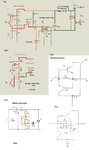
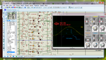
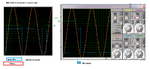
Please see the image Fig 1. Suposedly when the signal coming from 220V circuit comes to zero, wouldn't the capacitor should be discharged near enough from zero, then charge it in the oposite side? So, Isn't it sinchronic with the phase? We are attaching the optocoupler to this signal, so it should be sinchronic, or I'm wrong? Otherwise I could eliminate opto and connect as the original circuit in Fig 5, wich is one recomended here, but the first time the power stage fails, could burn everything, or What do you think about?
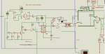
The problem I see is that the transistor only conduces in one way, I found in internet the arrangement in Figs 3 and 4. Would it be an option? Or finally, I could put a relay being drived by the transistor and this becomes transparently bidirectional just for a little bit more than half a pound
> Third problem, you seem to be trying to control the current through your optocoupler LED using
> transistors working from an AC supply
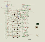
The optocoupler is not intended to be used as a variable resistance, but with variable signal, (if you compare Fig1 with Fig 2, you see that the selection of the transistors becomes just a digipot) so it would light when the current be enough. (maybe to add a shmitt tr.) I would have to see if the current through this resistors is enough to light it up or if it is too much. Once up, it would have to light up the triac, and the rest of half phase is a work of this last.
> you appear to limit it to only one of eight possible output steps when it is possible to have 256.
yes, I could use it as a much more resolution device but 8 steps are enough for now because I only pretend to move the power about 8%.
> if you really did want the outputs of the comparators to work the other way around, just swap the > inputs over!
Ok, thank you for the observation.
I don't know how to be more grateful to all of you, but thank you again.
Let me say that the more advanced pedagogic theories point to something named "autonomous education", wich means that the ones who knows go together with the ones learning by their own steps, instead of asignaturres and tests, and I think this is one of the more simmilar experiences to it. Thats it: you could ask for some money from government as all of you are giving a service of public interest under the most advanced pedagogic theories.
Have a good week
Sincerly
Luis J I
Do you think 70% and up is to much degree or maybe it works?
I'll read what you recomend me...
> ...There may be a border condition where it randomly fires
Please see the image Fig 1. Suposedly when the signal coming from 220V circuit comes to zero, wouldn't the capacitor should be discharged near enough from zero, then charge it in the oposite side? So, Isn't it sinchronic with the phase? We are attaching the optocoupler to this signal, so it should be sinchronic, or I'm wrong? Otherwise I could eliminate opto and connect as the original circuit in Fig 5, wich is one recomended here, but the first time the power stage fails, could burn everything, or What do you think about?
The problem I see is that the transistor only conduces in one way, I found in internet the arrangement in Figs 3 and 4. Would it be an option? Or finally, I could put a relay being drived by the transistor and this becomes transparently bidirectional just for a little bit more than half a pound
> Third problem, you seem to be trying to control the current through your optocoupler LED using
> transistors working from an AC supply
The optocoupler is not intended to be used as a variable resistance, but with variable signal, (if you compare Fig1 with Fig 2, you see that the selection of the transistors becomes just a digipot) so it would light when the current be enough. (maybe to add a shmitt tr.) I would have to see if the current through this resistors is enough to light it up or if it is too much. Once up, it would have to light up the triac, and the rest of half phase is a work of this last.
> you appear to limit it to only one of eight possible output steps when it is possible to have 256.
yes, I could use it as a much more resolution device but 8 steps are enough for now because I only pretend to move the power about 8%.
> if you really did want the outputs of the comparators to work the other way around, just swap the > inputs over!
Ok, thank you for the observation.
I don't know how to be more grateful to all of you, but thank you again.
Let me say that the more advanced pedagogic theories point to something named "autonomous education", wich means that the ones who knows go together with the ones learning by their own steps, instead of asignaturres and tests, and I think this is one of the more simmilar experiences to it. Thats it: you could ask for some money from government as all of you are giving a service of public interest under the most advanced pedagogic theories.
Have a good week
Sincerly
Luis J I