mamech
Full Member level 3

- Joined
- Nov 9, 2010
- Messages
- 176
- Helped
- 0
- Reputation
- 0
- Reaction score
- 0
- Trophy points
- 1,296
- Activity points
- 3,135
hello
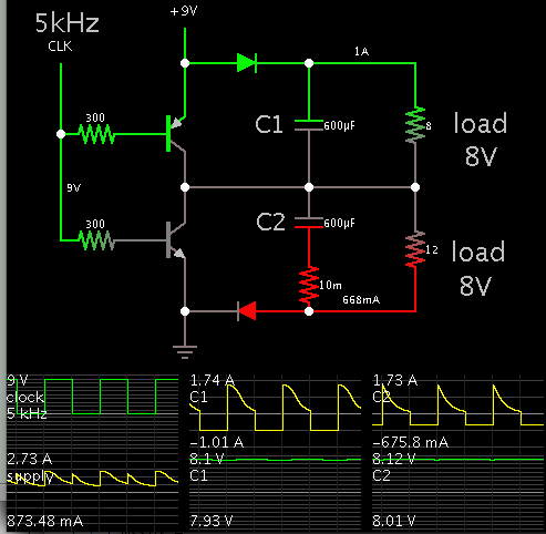
I made a dual power supply by making voltage divider to create a virtual ground, and then I made the a opamp for buffering to prevent this virtual ground to have loading effect.
everything worked great. the only problem is that i have now , is that I am restricted by the maximum current that can be drawn from op amp. for example, i tried to make position controller for a DC motor (similar to this circuit https://www.bing.com/images/search?...7E12BFB923A397D2B164CE6B90103&selectedIndex=0), and the motor hardly starts rotation!
I liked very much the idea of splitting supply using divider and op amp. is there any modification that I can do so the circuit can produce more supply?
Actually from my search , I found some suggestions :
1- to use power amplifier :
i have no experience about power amplifiers, can I replace my lm324 opamp (that I used to isolate the virtual ground) and use TBA820 instead? Can TBA820 to be used as a in normal buffer configuration like normal opamps ??
datasheet : https://www.ram-e-shop.com/ds/ic/TBA820.pdf
2- to use voltage regulator (like 7805 for ex)
The main problem that I noticed in this method, is that if I use it with 9volts dc supply, I think it will split it to +4volts and -5volts, which is not something good to have this difference. is there any solution that makes them equally divided without affecting the maximum current that can be drawn?
thanks for help


