Iulian Cepoiu
Newbie level 4

- Joined
- Oct 26, 2014
- Messages
- 5
- Helped
- 0
- Reputation
- 0
- Reaction score
- 0
- Trophy points
- 1
- Location
- Romania
- Activity points
- 31
hi
I am new here and was wondering if you can help me with this error (PSPICE)
ERROR -- Convergence problem in transient bias point calculation
Last node voltages tried were:
These devices failed to converge:
X_U1.dc X_U1.de X_U1.dlp X_U1.fb X_U1.q1 X_U1.q2
I am new here and was wondering if you can help me with this error (PSPICE)
Code:
**** INCLUDING pac-SCHEMATIC1.net ****
* source PAC
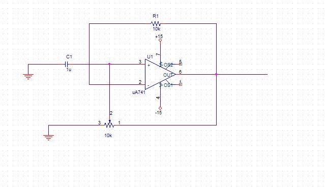
C_C1 GND N00143 1u
R_R1 N00246 N00290 10k
X_10k N00290 GND N00143 SCHEMATIC1_10k
X_U1 N00143 N00246 +15 -15 N00290 uA741
.subckt SCHEMATIC1_10k 1 2 t
RT_10k 1 t {(1K*(1-0.5))+.001}
RB_10k t 2 {(1K*0.5)+.001}
.ends SCHEMATIC1_10k
**** RESUMING pac-SCHEMATIC1-pac.sim.cir ****
.END
**** 10/26/14 16:55:42 ************** PSpice Lite (Mar 2000) *****************
** Profile: "SCHEMATIC1-pac" [ C:\pac-SCHEMATIC1-pac.sim ]
**** Diode MODEL PARAMETERS
******************************************************************************
X_U1.dx
IS 800.000000E-18
RS 1
**** 10/26/14 16:55:42 ************** PSpice Lite (Mar 2000) *****************
** Profile: "SCHEMATIC1-pac" [ C:\pac-SCHEMATIC1-pac.sim ]
**** BJT MODEL PARAMETERS
******************************************************************************
X_U1.qx
NPN
IS 800.000000E-18
BF 93.75
NF 1
BR 1
NR 1
CN 2.42
D .87ERROR -- Convergence problem in transient bias point calculation
Last node voltages tried were:
NODE VOLTAGE NODE VOLTAGE NODE VOLTAGE NODE VOLTAGE
( +15) 3.210E+06 ( -15) 3.210E+06 ( GND) 3.210E+06 (N00143) 3.210E+06
(N00246) 3.210E+06 (N00290) 3.210E+06 (X_U1.6) -.0124 (X_U1.7) 3.210E+06
(X_U1.8) 3.210E+06 (X_U1.9) 0.0000 (X_U1.10) 3.210E+06
(X_U1.11) 3.210E+06 (X_U1.12) 3.210E+06
(X_U1.13) 3.210E+06 (X_U1.14) 3.210E+06
(X_U1.53) 3.210E+06 (X_U1.54) 3.210E+06
(X_U1.90) 290.0E-06 (X_U1.91) 40.0000
(X_U1.92) -40.0000 (X_U1.99) 3.210E+06
These voltages failed to converge:
V(GND) = 10.00GV \ 3.210MV
V(N00143) = 10.00GV \ 3.210MV
V(N00246) = 10.00GV \ 3.210MV
V(N00290) = 10.00GV \ 3.210MV
V(X_U1.11) = 10.00GV \ 3.210MV
V(X_U1.12) = 10.00GV \ 3.210MV
V(X_U1.6) = 14.89KV \ -12.35mV
V(X_U1.7) = 10.00GV \ 3.210MV
V(X_U1.53) = 10.00GV \ 3.210MV
V(X_U1.54) = 10.00GV \ 3.210MV
V(X_U1.90) = 2.363KV \ 290.03uV
V(-15) = 10.00GV \ 3.210MV
V(+15) = 10.00GV \ 3.210MV
V(X_U1.99) = 10.00GV \ 3.210MV
V(X_U1.10) = 10.00GV \ 3.210MV
V(X_U1.13) = 10.00GV \ 3.210MV
V(X_U1.14) = 10.00GV \ 3.210MV
V(X_U1.8) = 10.00GV \ 3.210MV
These supply currents failed to converge:
I(X_U1.egnd) = -3.070mA \ -643.99pA
I(X_U1.vb) = -2.232A \ -123.50nA
I(X_U1.vc) = -2.277A \ -54.37uA
I(X_U1.ve) = 60.22mA \ -54.24uA
I(X_U1.vlim) = 2.363A \ 290.03nA
I(X_U1.vlp) = 2.323nA \ -40.00pA
I(X_U1.vln) = -2.403nA \ -40.00pA
I(X_U1.hlim) = -4.726nA \ -580.16e-18A
These devices failed to converge:
X_U1.dc X_U1.de X_U1.dlp X_U1.fb X_U1.q1 X_U1.q2
ERROR -- Discontinuing simulation due to convergence problem