Monady
Advanced Member level 4

- Joined
- Dec 1, 2008
- Messages
- 109
- Helped
- 12
- Reputation
- 24
- Reaction score
- 3
- Trophy points
- 1,298
- Activity points
- 2,151
Hi,
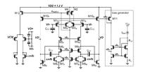
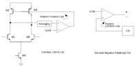
I'm going to design an opamp to be used in a continuous time system. I have seen several different structures for the CMFB part, including the one attached below. I want a CMFB which has a wide dynamic range, so I guess I need to use resistive averaging, but still I have a few questions:
What should frequency response of the CMFB circuit look like, I mean compared to the main opamp, should it have the same GBW, ...?
Besides, say in the case of the circuit shown below, for how much variation of the Vb1, CMFB should still be able to set the common mode of the output (VO+ and VO-) constant?
I have also seen some other structures that instead of using two diode-connected transistors in the CMFB, they used one single stage opamp (using just one diode connected), which one is more reliable?
Thanks!

