Continue to Site

Welcome to EDAboard.com

Welcome to our site! EDAboard.com is an international Electronics Discussion Forum focused on EDA software, circuits, schematics, books, theory, papers, asic, pld, 8051, DSP, Network, RF, Analog Design, PCB, Service Manuals... and a whole lot more! To participate you need to register. Registration is free. Click here to register now.

Constant current circuit

Status
Not open for further replies.

ramu651971

Newbie level 3
Joined
Dec 7, 2013
Messages
4
Helped
0
Reputation
0
Reaction score
0
Trophy points
1
Activity points
28
Hi All,
I am looking for a low constant current source,the requirement is
DC volts 18 35 75 125 150 200
Milli amps 0.5 1 2 5 10 20

Can anyone help me how to proceed?

Requirement is for Resistivity meter for ground water exploration

Regards,
Ramu
 
Last edited:
"Requirement is for Resistivity meter for ground water exploration", you must use AC or you will get polarisation on the electrodes. In either case the easiest way is to get more then 200 V then stabilise it then just feed it through a suitable high value resistor. This could be enough for your application as you do not specify your tolerance of the set current or the output impedance. With the high voltage and low current requirements, I would go for a shunt stabiliser, because 300V, 50 mA transistors are cheap and the circuit should be indestructible!
Frank
 

Thanks Frank,
I have read some papers where it has mentioned an AC square wave oscillator with 128hz frequency needs to be used for supplying current to the soil.Can you give me some idea how to achieve this alongwith circuit diagram
 

The industrial meters I have used have used 1000 HZ square wave or 50 HZ sinewave. The wave form is not important neither is its frequency, although it should not be too high else capacitive losses because a problem.
Have you worked out the likely range of the ground conductance? with this value and the correction factor of your probes, you then can work out the likely range of resistance your are dealing with.
I have only dealt with the conductance of de-ionised water which can be a rather good insulator, 2µ Mhos was our spec. (~500 KΩ) limit. drinking water was 600µ Mhos. So from these figures I would say that dry sand was better the 10 MΩ , and wet soil, higher then 1K.
If I was doing this job, I would use a common or garden DVM to measure the volt drop between your probes, and feed them, from say 20V low frequency sinewave, via a series of resistors. providing the voltage source is constant, relative conductivities can be made quickly, and if super accurate measurement are required a bit of maths can compensate for the change of current.
The problem is a high voltage sine wave oscillator (as I guess you want it to be battery powered), The actual waveform is not critical sine /square.. but is would be useful if its level was stabilized. it is extremely likely that you will need some sort of transformer to get from battery voltages to some thing over 20V AC .
lets see what the combined brains of this forum can suggest :)
Frank
 

Dear Frank,
Belated Christmas wishes,Wishing you a Happy New Year.
These days i was trying to understand the power supply requirement for the resistivity meter.As you said yes AC voltage with a max current 20mA wil serve the needs.
I request your help how to go ahead with the below given requirement:-
AC Voltage - 180Volts,Square wave,frequency some where else between 110 to 140hz,preferring 137hz
Current selectable = 0.2,0.5.1,2,2,10,20mA

If possible if you can suggest circuit will be great,basically i am mechanical engineer..........interested in electronics

Ramesh
 

Dear Friends,
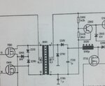
Can anyone help,which is type of transformer is shown in the diagram,i am not able to make it out.


transformer.jpg
 

Status
Not open for further replies.

Similar threads

Part and Inventory Search

Welcome to EDABoard.com

Sponsor

Back
Top