Continue to Site

Welcome to EDAboard.com

Welcome to our site! EDAboard.com is an international Electronics Discussion Forum focused on EDA software, circuits, schematics, books, theory, papers, asic, pld, 8051, DSP, Network, RF, Analog Design, PCB, Service Manuals... and a whole lot more! To participate you need to register. Registration is free. Click here to register now.

Connecting two solar panel in parallel to get more current. Please see!

Status
Not open for further replies.

navienavnav

Member level 1
Member level 1
Joined
Dec 12, 2011
Messages
36
Helped
1
Reputation
2
Reaction score
1
Trophy points
1,288
Location
India.
navneetkhare.co.cc
Activity points
1,627
I have two 5.5V 210 mA (under peak sunlight) solar panels which I bought off eBay just for fun. I wanted to connect these two in "parallel" to gain more current when both the panels are placed under the sun. But, let's suppose that one of the solar panel produces slightly less voltage than the other. In this case, the solar panel which is producing more voltage will instead force some current into the other solar panel, which won't be good and waste one solar panel's purpose. I thought of placing a blocking diode to prevent this reverse flow of current but it still is going to ruin the purpose of the parallel connection of the panels as the panel producing lower voltage will just be cut off (am i right?) due to the diode in such a case. Is there a simple (not involving complex ICs) way of still getting maximum current output from this setup? :razz:
 
Last edited:

Put the diode inline with the panel that puts out higher voltage.

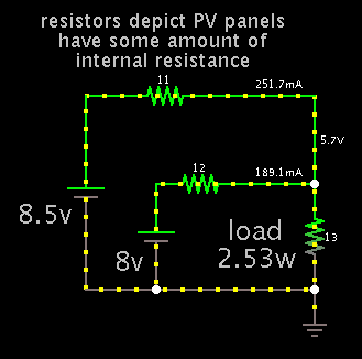
Situation at beginning where one panel is stronger. It puts out slightly higher voltage and has less internal resistance.

2129626600_1366739519.png


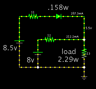
Diode installed inline with stronger panel. The diode wastes a small amount of power.

5094050600_1366739782.png


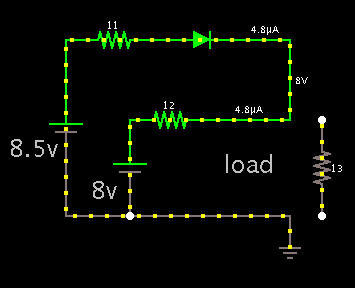
Load removed to show there is virtually no backflow into weaker panel:

1860352200_1366739863.png
 
Thank you so much for this! And with diagrams! You couldn't possibly have done more! I'll try this out ASAP. Thanks so much! I'll let you know if things don't work out. But i don't understand, when the load is disconnected, the diode is still forward-biased, right? Then how come the amount of current going through the lower panel so low? And for how much (potential difference) difference between the higher and lower outputting panels will this circuit be feasible? Like in this case, the difference between the two is .5. If we denote this with a variable x, then how much in magnitude can we make this 'x' and still expect decent working of this circuit?
 

But i don't understand, when the load is disconnected, the diode is still forward-biased, right? Then how come the amount of current going through the lower panel so low? And for how much (potential difference) difference between the higher and lower outputting panels will this circuit be feasible? Like in this case, the difference between the two is .5. If we denote this with a variable x, then how much in magnitude can we make this 'x' and still expect decent working of this circuit?

The diode is an easy way to reduce a DC supply by 0.6 V.

A common silicon diode creates a voltage drop of 0.6V. (There are other types of diodes which create different voltage drops).

If the difference between the panels is more than 0.6V, then the strong supply will overcome the voltage drop, and you may need to add a second diode.
 
Status
Not open for further replies.

Similar threads

Part and Inventory Search

Welcome to EDABoard.com

Sponsor

Back
Top