Continue to Site

Welcome to EDAboard.com

Welcome to our site! EDAboard.com is an international Electronics Discussion Forum focused on EDA software, circuits, schematics, books, theory, papers, asic, pld, 8051, DSP, Network, RF, Analog Design, PCB, Service Manuals... and a whole lot more! To participate you need to register. Registration is free. Click here to register now.

Confusion related to Single and Dual Supply OP-AMPS

Status
Not open for further replies.

Johnny101

Member level 1
Joined
Jul 13, 2014
Messages
34
Helped
0
Reputation
0
Reaction score
0
Trophy points
6
Activity points
356
Hi guys,

I have made a few general observations related to the usage of single supply and dual supply op-amps and wanted to know if I am moving in the right direction. Please correct me where wrong.

- If input signal is positive and has no -ve part then single and dual supply op amps are analogous?
- If signal is single ended (having both -ve and +ve part) and we have a single supply op amp - just bias the op amp at half the supply?
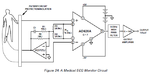
- If signal is differential (having both -ve and +ve part) and we have a single supply op amp what do we do now?
Could we add an offset to the input signal before giving it into the op-amp?
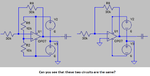
- If we have a dual supply op-amp it doesn't matter what type the input is?

Thanks in advance.
 

Hi,

single supply..dual supply.
An OPAMP has two supply pins. And it has no GND (supply) pin.
So talking about the supply ... the OPAMP doesn´t know what GND potential is.
So it doesn´t care if you use two 6V supplies or one 12V supply.

BUT
since an OPAMP has no GND pin connection one needs a voltage or a signal to reference to.
But this is a rather "therotical" reference.

See the picture below.
I´ve done a LTspice simulation.
Three time the same circuit:
* OP07 (any other OPAMP that can handle 12V total supply voltage will do) .
* same input circuit 100n in series with 10k to IN-
* same feedback circuit: 30k
* same circuit for IN+: 10k from positvie supply and 10k to negative supply.
* same output circuit 100n and 10k to GND
OP_SUPP.png

But all three have different power supplies.
* The first: single supply GND and +12V
* the middle: dual supply, +6V and -6V
* the right: single supply -12V and GND

But the output of all the circuits measured at the resistors is the exactely same.
And all OPAMPs do exactely the same.
Seen from each OPAMP´s view (onle the 5 nodes) there is no difference.

The difference is the point of the GND connection ... and thus the point to which the user referes the voltage measurement.

--> conclusion: Any standard OPAMP is able to operate on dual supplies as well as single suppliy.

***

A small test:
go to the left circuit and measure the voltage between -Supply and OUT: you will see the signal has an offset of +6V and swings with an amplitude of 3V
now go to the middle circuit and measure the voltage between -Supply and OUT: you will see the signal has an offset of +6V and swings with an amplitude of 3V
now go to the right circuit and measure the voltage between -Supply and OUT: you will see the signal has an offset of +6V and swings with an amplitude of 3V
--> from the OPAMP´s view its every time the same.

***

I hope this post doesn´t lead to more confusion than the single_supply / dual_supply specifications in the datasheets....


Klaus
 
@KlausST Thanks for such a detailed reply a few confusions are cleared now. But suppose I have a signal which is differential like an ECG signal having -2.5mV to 2.5mV signal range and I only have a 3V coin cell for driving my circuit. Now I give 3V to one pin of the op amp and 0V to the other pin. This would clip the -ve part of my signal. So what do you suggest I do. I could give 1.5V and -1.5V but again I don't think there are such low voltage operating op amps.
 

Hi,

this is a very common problem.

Especially with ECG circuits, there are solutions in the internet.
I´m not very experienced with ECG.
If I remember right there is a connection (electrode) at the patient to give a valid voltage reference. (is it right leg?)
Just drive this signal with VCC/2 (generated with voltage divider, OPAMP and RC and ESD protection to leg).
I think you can find the circuit here in the forum, but at least in the internet.

With this circuit you create an offset of to the ECG signals so they travel around VCC/2. Use an instrumentation OPAMP (circuit) to amplify your signals.


Klaus
 
An important specification for an opamp is the range of its useable input voltage. Some opamps have a limited input voltage range that might be 3V or more away from a positive or negative supply pin like a 741 opamp then if it has a single positive supply its inputs do not work if their voltage drops below +3V. But some opamps (like an LM324 or LM358) have inputs that work all the way down to the negative supply voltage that can be ground (0V). The opamp is usually biased at half the supply voltage that is ground (0) when there is a dual polarity supply.

Most ECG circuits use an instrumentation amplifier that has excellent common-mode interference rejection because a patient picks up a lot of common-mode (on both signal wires) interference. Interference is fed out-of-phase to the patient's right leg to cancel any remaining common-mode interference including DC from muscle movements.
 

Attachments

  • ECG circuit.png
    ECG circuit.png
    25.4 KB · Views: 96
  • dual supply opamp.png
    dual supply opamp.png
    13.8 KB · Views: 97
@Audioguru I am using a dual supply instrumentational amplifier (INA128) giving -5V and 5V at supply and things are working good but now I want to move to the single supply Instrumentational amplifier INA122 so that I don't have to use 2 batteries. But since the ECG signal is differential so using INA122 would actually clip the -ve part, so I somehow need to give an offset to the ECG signal. As mentioned by KlausST that I should attach the right leg to Vcc/2 which I am currently connecting to the ground. Would that work?
 

I think everything that has a "half the supply voltage" in the dual supply circuit including the instrumentation amp reference voltage pin should also be at "half the supply voltage" in the single supply circuit like this:
 

Attachments

  • ECG with dual and single supply.png
    ECG with dual and single supply.png
    37 KB · Views: 153
You are essentially lifting the ground to +5V. Nothing wrong and it should and will work except every time for some reason or other you touch the machine. ECG potentials are usually of the order of a few mVs and touching the machine will create some ripple ...
 

A small test:
go to the left circuit and measure the voltage between -Supply and OUT: you will see the signal has an offset of +6V and swings with an amplitude of 3V
now go to the middle circuit and measure the voltage between -Supply and OUT: you will see the signal has an offset of +6V and swings with an amplitude of 3V
now go to the right circuit and measure the voltage between -Supply and OUT: you will see the signal has an offset of +6V and swings with an amplitude of 3V

OUT1=OUT2=OUT3

Left circuit: -Supply=0 V, OUT1=swing 3 V of amplitude => -Supply-OUT1=-OUT1 which means swings 3 V of amplitude and phase 180º. Where is the +6V of offset?

Middle circuit: -Supply=-6 V, OUT1=swing 3 V of amplitude => -Supply-OUT1=-6-OUT1 Where is the +6 V of offset ?

Right circuit: -Supply=-12 V, OUT1=swing 3 V of amplitude => -Supply-OUT1=-12-OUT1
Where is the +6V of offset?
 

@Audioguru I had actually tried the same circuit that you have given and it also works in simulation but don't know why it is not working in hardware I hooked up the ref pin using a voltage divider and a voltage buffer for low impedance as given in the datasheet but still no results. Is there a possibility that there is some difference in b/w the INA128 and AD620 but they seem analogous!
 

Hi,

OUT1=OUT2=OUT3
not true.

Each OPAMP output has a different DC offset referenced to GND.
Each OPAMP output has the same DC offset referenced to it´s -Supply.

Klaus
 
  • Like
Reactions: CataM

    CataM

    Points: 2
    Helpful Answer Positive Rating
Status
Not open for further replies.

Similar threads

Part and Inventory Search

Welcome to EDABoard.com

Sponsor

Back
Top