Continue to Site

Welcome to EDAboard.com

Welcome to our site! EDAboard.com is an international Electronics Discussion Forum focused on EDA software, circuits, schematics, books, theory, papers, asic, pld, 8051, DSP, Network, RF, Analog Design, PCB, Service Manuals... and a whole lot more! To participate you need to register. Registration is free. Click here to register now.

[PIC] confusion about reading ac mains voltage with microcontroller

Status
Not open for further replies.

jit_singh_tara

Full Member level 6
Full Member level 6
Joined
Dec 22, 2006
Messages
325
Helped
9
Reputation
18
Reaction score
4
Trophy points
1,298
Location
Delhi , India
Visit site
Activity points
4,295
Hello frnds ,

Please clarify my doubt :

If we want to measure ac mains voltage rms .

1.We scale down 240Vac RMS(340V Peak) to say 3.53 AC RMS( 5V peak).
2. Now if we want to read this peak voltage which is with respect to neutral ,from adc of microcontroller , then since uC runs on 5V and Gnd , Will uC be able to read the 5V peak ac voltage .

What about the neutral of scaled 5v ac , and gnd of uc supply .

Can we read directly from mcu as the neutral and gnd are at different potential , or are they at same potential.
If they are at same potential can we connect them together Gnd and Neutral of the scaled 240V ac mains......


Please clarify how to read ac mains voltage directly from microcontroller adc for rms voltmeter.

thanks....
 

Don't confuse "common" and "neutral" and "ground". But forget all that for the moment.

I would suggest you use an isolation transformer; then you can connect one side of the secondary to your uP common, and the other side to your ADC input. And I would scale this to something less than a 5V output, otherwise you won't be able to distinguish between 240V and 260V.
 

Hi,

don´t forget that 230V AC also means -340V peak. so peak-to-peak is 680V.
Your ADC probably has only 0..5V input.

To get around this you acn use a resistor devider to downscale the mains voltage to +/- 2.5V.
Then a capacitor to ADC input, and also high ohmic bias voltag of 2.5V to the ADC input.
Then you see the 2.5VDC added with +/-2.5V AC. Mind to subtract the offset in software.

Hope this helps.
And take care of you - 230V is dangerous!

Klaus
 

i am posting pics of the design....

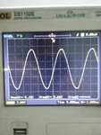
a.here is the pic of scaling down 240V rms ac to 3.65V rms (approx 5V peak).

240 v ac rms  scaled to 3.65V ac rms (5v peak).jpg

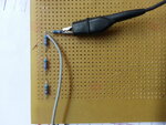
measuring the voltage on oscilloscope as shown in figure below .with respect to neutral.


240V to 5v resistor divider.jpg


This much part is fine i am able to scale the ac voltage down to 5v peak ac wrt neutral .i.e oscillosope one lead to neutral and other lead to the resistor divider...

- - - Updated - - -

The problem is how do i connect this scaled voltage to :

1. LM324 circuit , which i am using to add an offset so that i can have the waveform going from 0v to 5V positive peak only .i.e
a. -5V peak : 0V .
b. 0V : 2.5V .
c. +5V peak : 5V .

I am again scaling down the 10V peak to peak ,of this 5V peak waveform as shown above post .

The problem is that when i connect this scaled ac voltage directly to opamp circuit the wave form output from the opamp is very distorted , it is no more a sine wave ,
i am running my lm324 with +-8V supplies.
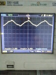
I will post the pic as shown below the moment i connect my opamp pin2 through the resistor 2k .

distorted waveform.jpg

I want to make a true rms meter , plz help me how to read the samples of the waveform , how to get a perfect waveform.....


Can i connect neutral to ground ? I know sounds strange but how do i measure ac voltage with uC which measures according to the ground .
 

hello,

use a transformer 230/9V (or 6V) to follow a safety situation...

i did a peak to peak measurment an obtain results like this

20:57:45.519> Projet:18F26K22 UART1 BT
20:57:45.581> Version 230V 50Hz
20:57:45.644> Port Com ouvert & Init HARDW.
20:57:48.019> Init PCF8574 correcte Adresse=4E j= 1
20:57:48.019>
20:57:58.269>
20:57:58.394> Coeff Calibration =0.2596
20:58:02.394> N=00290 L=00000 Maxi=0968 Mini=0055 Peak2Peak=0913 Voltage = 237.0
20:58:03.206> N=00290 L=00001 Maxi=0968 Mini=0056 Peak2Peak=0912 Voltage = 236.7
20:58:04.019> N=00290 L=00002 Maxi=0962 Mini=0062 Peak2Peak=0900 Voltage = 233.6
20:58:04.831> N=00290 L=00003 Maxi=0968 Mini=0055 Peak2Peak=0913 Voltage = 237.0
20:58:05.644> N=00290 L=00004 Maxi=0968 Mini=0057 Peak2Peak=0911 Voltage = 236.5
20:58:06.519> N=00290 L=00005 Maxi=0967 Mini=0060 Peak2Peak=0907 Voltage = 235.4
20:58:07.331> N=00290 L=00006 Maxi=0961 Mini=0062 Peak2Peak=0899 Voltage = 233.3
20:58:08.144> N=00290 L=00007 Maxi=0968 Mini=0056 Peak2Peak=0912 Voltage = 236.7

all details on my web page..C18 code

Mesure_Secteur_50Hz.jpg
 
Hi,

here a picture with opamp as buffer.
SCHEM1.PNG

To make it even easier you can leave the opamp and connect the signal Opamp+ directely to ADC.

This is a low cost solution with good results, but no safety and no filters...

Hope this helps
Klaus
 

Status
Not open for further replies.

Similar threads

Part and Inventory Search

Welcome to EDABoard.com

Sponsor

Back
Top