Welcome to our site! EDAboard.com is an international Electronics Discussion Forum focused on EDA software, circuits, schematics, books, theory, papers, asic, pld, 8051, DSP, Network, RF, Analog Design, PCB, Service Manuals... and a whole lot more! To participate you need to register. Registration is free. Click here to register now.
The easiest way to define a coplanar waveguide port is to pick the two innermost substrate corners of the outer conductors. After picking the geometry, you can now open the port definition dialog box (Solve > Waveguide Ports). In this dialog box, simply select the port’s normal direction and orientation before you specify an extension of the port around the picked geometry by entering the distances in the corresponding entry fields.
You need an extension space of ideally the width of the inner conductor plus the gaps line at each side of the inner conductor line. Furthermore, you should specify a distance of half of the width of the inner conductor plus the gaps above and below the inner conductor.
In the case of grounded coplanar lines, make sure to enter exactly the height of the substrate for the port extension below the inner conductor or you might introduce some unwanted additional space between the substrate and the ground metallization, or the port may not be connected to ground at all.
The explanations above mainly refer to unshielded coplanar lines. When a shielded coplanar line problem needs to be simulated, the port can be normally chosen so that it covers the entire dimension of the structure. The physical problem of unwanted box resonances appears much earlier in these cases than the artificial problem of unwanted propagating modes so that you do not need to worry about the latter here.
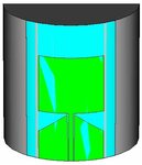
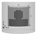
have you noticed that the antennas in the attached photos are in non-planar form ? both antennas are on cylindrical substrate ? so is the using of conventional CPW is correct?
I know how to set the CPW port for conventional planar antenna and my question was about the CPW port for curved antenna?
What if I'm using a patch antenna fed from bottom, and the antenna array is conforming to a cylindrical shape? i tried to replace with discrete port but when a number rotation is being done, there seems to be slight error with the discrete port alignment.
This site uses cookies to help personalise content, tailor your experience and to keep you logged in if you register.
By continuing to use this site, you are consenting to our use of cookies.