Continue to Site

Welcome to EDAboard.com

Welcome to our site! EDAboard.com is an international Electronics Discussion Forum focused on EDA software, circuits, schematics, books, theory, papers, asic, pld, 8051, DSP, Network, RF, Analog Design, PCB, Service Manuals... and a whole lot more! To participate you need to register. Registration is free. Click here to register now.

Component on board is burn , Help !!!

Status
Not open for further replies.

haohaodk46

Member level 4
Joined
Apr 8, 2012
Messages
74
Helped
1
Reputation
2
Reaction score
2
Trophy points
1,288
Activity points
1,789
Hi All,
I have a RS485 network with 32 nodes
This is my circuit
1665221532583.png


This issue here is My board some days is burn some component on board

I use switching power supply like this to supply 24V for all nodes on bus
1665221958161.png


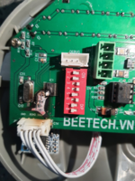
And Here is picture components is burned

z3781055938748_6e677ab7886959435b8f3fc93e70d9d7.jpg


1665222761508.png
on The bus have 32 nodes but just have 1 or 2 boards is burned.
And maybe about some days the other board is burn
There is any component is shorted and cause burn or over volatage 24V on board ?
Every one have explain why ? Help me !!!!
Thanks
 
Last edited by a moderator:

Hi,

Neither the numbers nor the values of schematic match with PCB.
At lest areound the buck regulator. Not to identify which regulator you use.
The capactiors don´t seem to suitable for high speed switching.

--> please provide consistent informations.

Klaus
 

Does damage happen spontaneously in operation or when first powering a new installed board? What's the total bus length? Do you identify a possible reason for 24V overvoltage?

I notice that RS485 lines have no overvoltage protection. Feeding 24V accidentally will possibly destroy many components connected to the 5V node.
 

Sorry I corrected again schematic
Capture.PNG

--- Updated ---

Does damage happen spontaneously in operation or when first powering a new installed board? What's the total bus length? Do you identify a possible reason for 24V overvoltage?

I notice that RS485 lines have no overvoltage protection. Feeding 24V accidentally will possibly destroy many components connected to the 5V node.

It happen spontaneously in operation . The length bus is about 70-80m.
Why is the component is destroy when without overvoltage protection because VCC for 485 IC is 5V ?
The Switch power supply often have current leakage and sock when touch in 485 bus , so maybe this point cause damage for component ?

Hi,

Neither the numbers nor the values of schematic match with PCB.
At lest areound the buck regulator. Not to identify which regulator you use.
The capactiors don´t seem to suitable for high speed switching.

--> please provide consistent informations.

Klaus
I correct schematic
 
Last edited:

Hi,

did you read the datsheet thoroughly?
Especially the thermal and PCB layout considerations.

Your "heatsink" is rather small. Did you do long term temperature tests under worst case conditions in an enclosure?
Also the fast ceramics capacitors are - for my taste - too far from the switching sources.
Hopefulle the bottom side is a GND plane. But I miss (multiple) vias for low impedance path to GND .. also I miss vias for heatsink purposes.

There´s a good chance that the switcher overheats and gets destroyed .. caussig high (24V) voltage to the ouput node (5V) ... cuasing a chain reaction in destroying othre devices.

I also recommend the RS485 protection. Here the +/-7V common mode range for the RS485 needs a somehow "special" protection circuit. Not the usual double diodes.

Klaus

Added:
I don´t recommend 100uF at the input and 1000uF at the output ... rather the other way round.
A 1000uF electrolytics (unless a special HF LOW ESR one) is almost useless for these switching frequencies.
You may rather see it a power supply backup for short supply failures.

I can´t agree with some statements of the datasheet. Especially PCB layout and capacitors. For example they call capacitor values (for SMPS!) of 200uF ... 1000uF as "low value". Honestly I guess I never used more than 100uF at all for DC DC SMPS. But this LM2576 uses rather low switching frequency .. I usually use much higher frequency ones. So in doubt: keep on the datasheet.
 
Last edited:

I'd use TVS diodes at the RS485 transceiver (e.g. 6.8V) and PTC fuses with 50 mA rather than 1A rating.

Surges at unprotected RS485 lines can damage the transceiver in the first place. To damage other 5V components, it must have enough energy to raise the 5V node to a dangerous level (> 7V). To damage LM2576, it must raise the 5V node above 24V or pull it below zero. That's rather unlikely for a short surge, much easier achieved with shorted or flipped bus lines. Live connect/disconnect of boards to the powered bus would be another possible explanation.
 

Hi,

This document:

Talks about -/..+12V "common mode voltage" but I always treated it a +/-7V common mode voltage (wrt GND) + 0..5V signal voltage (wrt GND) to give an absolute voltage range of -7 ... +12V for each input.

Thus the protection should allow -7 ... +12V at each input wrt GND.

And it should not use VCC as the path for protection, because on power supply fault of one bus partner the voltage levels for all the other partners should be maintained.

Klaus
 

I don´t recommend 100uF at the input and 1000uF at the output ... rather the other way round.
A 1000uF electrolytics (unless a special HF LOW ESR one) is almost useless for these switching frequencies.
You may rather see it a power supply backup for short supply failures.

I can´t agree with some statements of the datasheet. Especially PCB layout and capacitors. For example they call capacitor values (for SMPS!) of 200uF ... 1000uF as "low value". Honestly I guess I never used more than 100uF at all for DC DC SMPS. But this LM2576 uses rather low switching frequency .. I usually use much higher frequency ones. So in doubt: keep on the datasheet.
So what is capacitor value that you used for LM2576 ?
Do you think about switching power supply ? This power supply often have noise . is It ok if around environment have motor electric device. Does it impact ?
 

Hi,

first things first:
* use the protection on the RS485 lines.
* improve the PCB layout.

If heating is the problem, then no capacitor can avoid this
Also on this non optimal PCB layout (not following the datasheet guidelines) no capacitor can work "as a capacitor" because of the high series impedance of the PCB traces. So changing capacitors will have the most impact on a optimized PCB layout.
Mind: not the trace thickness, nor the trace width have big impact on the stray impedance, it´s the trace length and the combination with the return path (vias, GND_plane).

There are many, many threads here in this forum about circuit problems caused by PCB layout.

****
Do you think about switching power supply ?
LM2576 is a switching power supply.

Klaus
 

Hi,

first things first:
* use the protection on the RS485 lines.
* improve the PCB layout.

If heating is the problem, then no capacitor can avoid this
Also on this non optimal PCB layout (not following the datasheet guidelines) no capacitor can work "as a capacitor" because of the high series impedance of the PCB traces. So changing capacitors will have the most impact on a optimized PCB layout.
Mind: not the trace thickness, nor the trace width have big impact on the stray impedance, it´s the trace length and the combination with the return path (vias, GND_plane).

There are many, many threads here in this forum about circuit problems caused by PCB layout.

****

LM2576 is a switching power supply.

Klaus
1665408517974.png

I mean this power supply that supply 24v for all node on bus . This power quite noise, thus is ít cause over voltage in short time because noise ?
 

Status
Not open for further replies.

Similar threads

Part and Inventory Search

Welcome to EDABoard.com

Sponsor

Back
Top