Welcome to our site! EDAboard.com is an international Electronics Discussion Forum focused on EDA software, circuits, schematics, books, theory, papers, asic, pld, 8051, DSP, Network, RF, Analog Design, PCB, Service Manuals... and a whole lot more! To participate you need to register. Registration is free. Click here to register now.
I have made a controlled DC-DC boost converter circuit. But the plot in transient analysis and oscilloscope is different. How can I get same transient plot as CRO plot as i cannot get the datapoints from the CRO output.
"Different"
Please be more specific. Maybe it's just different "color"...
But it could also be different
* timing
* amplitude
* noise
* phase
* and a lot else...
As so often: pictures say more than a lot of words
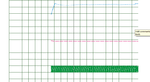
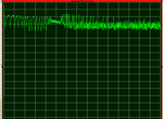
Different in terms of amplitude, noise and time domain response
Attaching the figure for CRO output(in first graph in CRO.png) and transient analysis plot(in transient.png) from the controlled boost converter
This site uses cookies to help personalise content, tailor your experience and to keep you logged in if you register.
By continuing to use this site, you are consenting to our use of cookies.