Continue to Site

Welcome to EDAboard.com

Welcome to our site! EDAboard.com is an international Electronics Discussion Forum focused on EDA software, circuits, schematics, books, theory, papers, asic, pld, 8051, DSP, Network, RF, Analog Design, PCB, Service Manuals... and a whole lot more! To participate you need to register. Registration is free. Click here to register now.

Comparot with ic16f877a

Status
Not open for further replies.

jean12

Advanced Member level 2
Joined
Aug 27, 2013
Messages
529
Helped
5
Reputation
12
Reaction score
6
Trophy points
18
www.ntigltd.com
Activity points
5,497
Hello there can,you lease help me to run the comparator module of PIC16F877A, I want to use the variable resistor connected on the AN0 and then sense the voltage and light a LED on PIN_D3 with the value of voltage read from the in.

Please help,here is the circuit.

Thanks.
 

Attachments

  • Comparator.zip
    14.7 KB · Views: 46

hello,

I don't know if comparators have same philosophy in 16F877 as for PIC18Fx6k22
maybe it can help you..
can you post your code..
Not all people have Proteus tools.. some works only in real world.

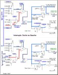
I tested Comparators Hardware functions with a joystick (2 potars) to drive a LCD Menu..
and used booth comparator interrupt and pooling comparator..
 

Attachments

  • 18F46K22_Interrupt_Comparators.jpg
    18F46K22_Interrupt_Comparators.jpg
    170.7 KB · Views: 57

hello,

I don't know if comparators have same philosophy in 16F877 as for PIC18Fx6k22
maybe it can help you..
can you post your code..
Not all people have Proteus tools.. some works only in real world.

I tested Comparators Hardware functions with a joystick (2 potars) to drive a LCD Menu..
and used booth comparator interrupt and pooling comparator..


hell sir,see the code:
PHP:
/*
 Project: A very basic clap switch
 Description : Clap switch using PIC1fF877A
 Oscillator: Internal 4.0000 MHz, MCLR Disabled, PWRT ON enabled
 Written by: Rajendra Bhatt (www.embedded-lab.com)
 Date:       SEPT 23, 2013
*/

#define Output_LED  PORTd.F2;
unsigned short i, TIME_UP;

void interrupt(void){
  if(PIR1.TMR1IF) {
    i ++;
    if(i == 3) TIME_UP = 1;  // Time Up in 1.5 sec
    PIR1.TMR1IF = 0;
 }
}

void main() {
  //TRISIO = 0b00000011 ;
  TRISA= 0b00000011 ;
  //ANSEL = 0x00;
  INTCON = 0b11000000 ; // Enable GIE and PEIE for Timer1 overflow interrpt
  PIE1 = 0b00000001 ;   // Enable TMR1IE
  //CMCON0 = 0b00010100;
  //CMCON = 0b00010100;     changed on my  own
       CMCON = 0b00010110;
 //CVRCON  = 0b10100011;
 CVRCON  = 0b10100010;
  //Output_LED = 0;
  PORTd.F2=0;
  do{
     TMR1H = 0x00;
     TMR1L = 0x00;
     TIME_UP = 0;
     i = 0;
     T1CON = 0b00110000;   // Configure Timer 1
     if(CMCON.C2OUT) {  // First clap detected
       Delay_ms(100);
       T1CON.TMR1ON = 1;   // Start Timer1
       while(!CMCON.C2OUT && !TIME_UP); // Wait until second clap is
       T1CON.TMR1ON = 0;  // detected or Timer1 overflows
       if(CMCON.C2OUT && !TIME_UP)
       //Output_LED = ~Output_LED;
       PORTc.F2=~PORTc.F2;
       Delay_ms(100);
     }
  } 
   while(1);
}
 

Status
Not open for further replies.

Similar threads

Part and Inventory Search

Welcome to EDABoard.com

Sponsor

Back
Top