Continue to Site

Welcome to EDAboard.com

Welcome to our site! EDAboard.com is an international Electronics Discussion Forum focused on EDA software, circuits, schematics, books, theory, papers, asic, pld, 8051, DSP, Network, RF, Analog Design, PCB, Service Manuals... and a whole lot more! To participate you need to register. Registration is free. Click here to register now.

Commercial products of dual voltage controlled current source in uA level

Status
Not open for further replies.

bhl777

Full Member level 6
Joined
Sep 30, 2008
Messages
363
Helped
0
Reputation
0
Reaction score
0
Trophy points
1,296
Activity points
5,140
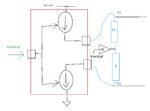
Hi All, I am looking for a commercial VCCS product, which include one current source and one current sink, with the same amplitude and can be controlled by a external DC voltage in generating uA level DC current. Would anyone give me some recommensation in finding this kind of product?
My application is to use the current source and sink to go thourgh two external resistros, in generating a window (between V1 and V2), while the amplitude level of the current can be controlled from an external signal.
VCCS.jpg
Thank you!
 

Hi,

In my eyes your circuit makes no sense.
Both current sources can never supply the exact same current, therefore one current source may saturate an drive it's output voltage near the supply rails.

Klaus
 

Even if both currents would be exactly equal, the circuit doesn't generate a "voltage window" rather than a voltage difference V1-V2 with unknown & floating absolute voltage somewhere between 0 and 5 V.

I'm not aware of ready made controllable current source ICs in the µA range. I designed similar circuits with OPs and transistors up to now.
 

Hi,
Have a look online to see if the pdf version appears of: "Current Sources and Voltage References" by Linden T Harrison, (IMO) a great book that is really well-written/explained, you may (or may not) find some ideas in there that you can adapt to your needs as suggested in the previous post.

Why not look into the REF200? While not adjustable, it has a multitude of "typical application" schematics with formulas, and one or two appear to include modifying the 100uA sink/source references, at a push you could use trimpots or whatever design you have in mind for the voltage control part.
 

Attachments

  • ref200.pdf
    1.5 MB · Views: 101
Last edited:
  • Like
Reactions: bhl777

    bhl777

    Points: 2
    Helpful Answer Positive Rating
Even if both currents would be exactly equal, the circuit doesn't generate a "voltage window" rather than a voltage difference V1-V2 with unknown & floating absolute voltage somewhere between 0 and 5 V.

I'm not aware of ready made controllable current source ICs in the µA range. I designed similar circuits with OPs and transistors up to now.

Hi FvM, would you tell me how you implement the similar circuits with OPs and transistors, that I can buy from online store to build it. A more accurate schematic is like this: I have a buffered voltage level, which sets the central level of this window. The current souce and sink are not necessarily exact the same but with minimized deviation. Thank you!VCCS.jpg

- - - Updated - - -

Hi,

In my eyes your circuit makes no sense.
Both current sources can never supply the exact same current, therefore one current source may saturate an drive it's output voltage near the supply rails.

Klaus

Hi Klaus,I just uploaded a different schematic to show my detailed circuit in the reply to FvM. Do you think if I use REF200 to build this circuit, is there any potential problems? Thank you!
 

Hi,

What benefit do you see in this circuit?
It's not a true current force anymore, and it is no voltage force. So it is something inbetween.

Can you tell us what the real function of your circuit should be?
Is this complicated circuit really useful?

Klaus
 

Hi,

What benefit do you see in this circuit?
It's not a true current force anymore, and it is no voltage force. So it is something inbetween.

Can you tell us what the real function of your circuit should be?
Is this complicated circuit really useful?

Klaus

Hi Klaus, I am trying to build a window to compare with a periodic ramp to generate PWM. I want to build this circuit for making an open loop buck converter for some bode plot measurement.
 

Hi,

The application note has a series of different circuits using op amps and the REF200, this link shows a set-up where the trimpot could be replaced with the control voltage input:

https://www.merghart.com/p/28/opamp-adjustable-current-source

It's just one example, there are loads of current source/sink circuits and application notes available by individuals and semiconductor manufacturers, many in pdf format.

You could look for op amp circuit collection app notes, they have lots of ideas, some which can be slightly modified easily to fit your needs.

Also, the LM134 or LM334 current reference IC, and voltage references like the 4041 or TL43 may have a wide range of "typical application" schematics in the datasheets that are simple to implement.

I like browsing op amp and voltage current ref, etc., app notes for things such as you wish to implement, or that "Current Sources and Voltage References" book, "print version" should bring it up in a search, as they are brimming with reliable, tested cicuits, it saves time inventing things that don't work or accidentally copying amateurish circuits from "dodgy" websites.

e.g. AN-31, snoa621c, A collection of Amp Applications

- - - Updated - - -

a window to compare with a periodic ramp

Hi, "FIGURE 37. Window comparator with voltage programmable window center, and resistor programmable window width". in the previously uploaded pdf, sounds like it could fit the bill, but need to change dual supply to single supply. I'm sure some-one would be glad help with that if you try and have difficulties getting it to function correctly.

Three more voltage controlled current sources using op amps, the first two are single supply, the third is dual supply so may or may not be adaptable to single supply operation.

https://www.daycounter.com/Circuits/Current-Servo/Current-Servo.phtml

https://www.tina.com/blog/voltage-controlled-current-source-circuit/

**broken link removed**

(for the third you need to click on "figure" to see the schematic in a new browser tab)

I think the "Implementations and applications...", figure 37 sounds closest to what you want to do, and looks easy to adapt via passive components, but is dual supply. In principle, I don't see that being so hard to adapt to single supply operation, window comparators are quite easy to make and adapt.

There are lots of free schematic capture (design) programs, some including simulation, it's worth spending an hour learning to use them to sometimes show others what you mean, by exporting a jpg. or pdf or whatever document format of the schematic. Problems only arise when you need to simulate a specific part that is not available in a program. LTSpice is schematic capture and simulation. TINA-TI is also both. DesignSpark is schematic capture and PCB design, and very easy to use after a short while, but most are, design is "easy", simulation not so much at all. There are many other free programs, there's a section here where they are discussed, could be helpful if you're interested.
 

Attachments

  • IMPLEMENTATION AND APPLICATIONS OF CURRENT SOURCES AND CURRENT RECEIVERS sboa046.pdf
    427.4 KB · Views: 39
Last edited:

If the resistors in the post #5 schematic are fixed, there's no need for current sources. V1 and V2 can be generated by voltage adder and substraction circuits.
 

Status
Not open for further replies.

Similar threads

Part and Inventory Search

Welcome to EDABoard.com

Sponsor

Back
Top