Continue to Site

Welcome to EDAboard.com

Welcome to our site! EDAboard.com is an international Electronics Discussion Forum focused on EDA software, circuits, schematics, books, theory, papers, asic, pld, 8051, DSP, Network, RF, Analog Design, PCB, Service Manuals... and a whole lot more! To participate you need to register. Registration is free. Click here to register now.

Colpitts's oscilator - frecuency

Status
Not open for further replies.

julian403

Full Member level 5
Joined
Feb 28, 2014
Messages
254
Helped
1
Reputation
2
Reaction score
1
Trophy points
18
Location
Argentina
Activity points
2,105
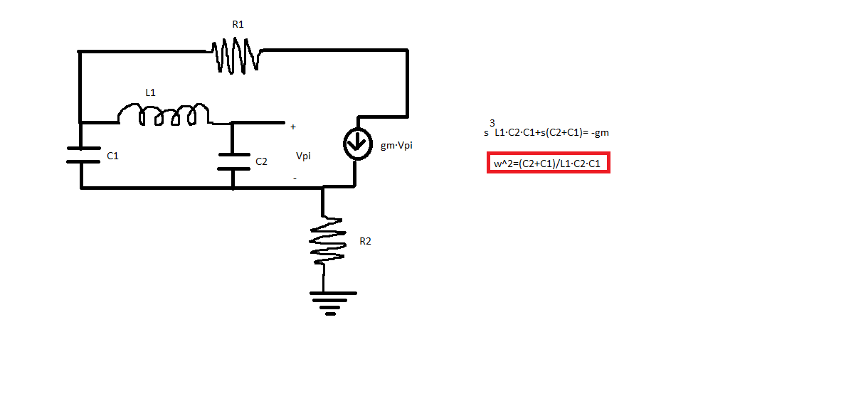
Using the colpitts's oscilator I get a frecuency of 145KHz

colpitts.png

but If I analize the resonance:

resonancia.png

Why there is that difference? If I take care of base-emitter's capacitance, there is not change because the resonance depends of L and C1
 

This sort of disparity is frequent, between math and simulator, or simulator and real hardware, etc. It might have to do with energy being drawn momentarily from C2, which goes to bias the transistor. The result is to discharge C2 a little more quickly, causing faster action and a faster oscillation frequency.
 
Its interesting, that oscillation will occur where the overall gain plus phase produces maximal feedback around the loop.

For various reasons the transistor plus its parasitics may contribute some extra phase delay around the loop, which can pull the frequency.

Another gremlin may be that the inductor has a core material that has a non linear BH curve, such that different levels of ac excitation can shift the inductance, even if there is no change in net dc.

There may also be significant capacitance between the turns of any real choke, that the simulation does not know about.

So you build a practical circuit and try different types of transistor, and different types of 22uH choke you might find that the oscillation frequency is all over the place.
Its a pretty normal outcome.
 
Another gremlin may be that the inductor has a core material that has a non linear BH curve, such that different levels of ac excitation can shift the inductance, even if there is no change in net dc.

Well, the inductor is a choke. Now know why it's better to use crystal (0.01% tolerance)

Another stuff. Where is the feedback? For which componet the signal has feedback.
 
Last edited:

The difference is too large and must be due to the variation of the component values. You need to measure accurately the component capacitances and inductance and plug in the equation. A small difference (~10%) may be explained due to loading and parasitic capacitance and the transistor phase shift.
 
You forgot to tell the calculation scheme used to determine the resonance frequency. I think it's simply wrong.

Its interesting, that oscillation will occur where the overall gain plus phase produces maximal feedback around the loop.
Strictly speaking at the frequency that fulfills the Barkhausen oscillation condition. That's not necessarily the frequency of maximum loop gain. The phase condition has to be met, too.

An exact loop gain calculation has to consider the transistor impedances and is a bit involved. Fortunately the characteristic LC impedance is relative low compared to the transistor circuit, so we can assume an oscillation frequency near the LC resonance. In my calculation it's 1/(2*pi*√(22uH*50nF)) = 151.7 kHz, quite near to observed frequency...
 
So, you are saying that the filter's resonance frecuency (made by C1 L and C2) it's 107KHz but the base emitter capacitance shift the phase and the frecuency changes?

In my calculation it's 1/(2*pi*√(22uH*50nF)) = 151.7 kHz, quite near to observed frequency...

Why did you take 50nF and not 100nF?

This it's the equivalent circuit that I made

equivalent.png
 

I have used the following model


Cmu and rPI are neglected, Cpi is assumed as a part of C2, r0=infinite (no early effect) . All this to simplify analysis even though they do not affect oscillating frequency.

At some point, I arrived to a close expression as yours in post #1...
 

This it's the equivalent circuit that I made
The circuit looks good. Apparently you didn't calculate it's resonance frequency correctly. I presume Cbe, Cce << 100 nF, also transistor input impedance is large against Xc, so the resonator capacitance is effectively a series circuit of two 100 nF capacitors.
 

The circuit looks good.
No, it does not.

1) Cmu = capacitance between base and collector in his circuit is infinity (short circuit), who says that ... rather is an open circuit

2) "hoe" is wrong because "hoe" has not dimensions of ohms, but siemens, it must be placed as 1/hoe = r0 (early effect)

3) The current dependant source is missing (gm·Vpi)

- - - Updated - - -

Forgot to say, 4) Cce capacitor is wrongly placed.
 
  • Like
Reactions: FvM

    FvM

    Points: 2
    Helpful Answer Positive Rating
Sorry, this it's the equivalent circuit
equivalent.png

What's the feedback path? And why FvM takes 50nF?
 

Attachments

  • equivalent.png
    equivalent.png
    5.6 KB · Views: 68

FvM takes 50 nF because the expression for the frequency is like in post #8.
ω²=(C1+C2)/L1·C1·C2
 
Status
Not open for further replies.

Similar threads

Part and Inventory Search

Welcome to EDABoard.com

Sponsor

Back
Top