Vermes
Advanced Member level 4
The colour-phone is easy to be home made. It is based on J-050.
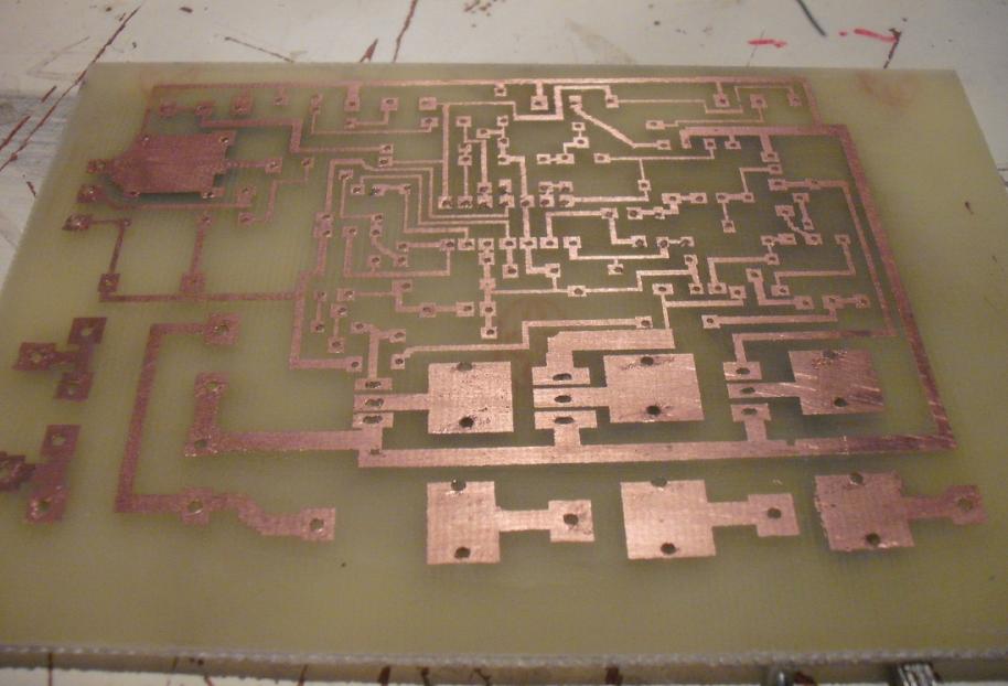
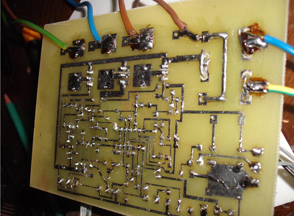
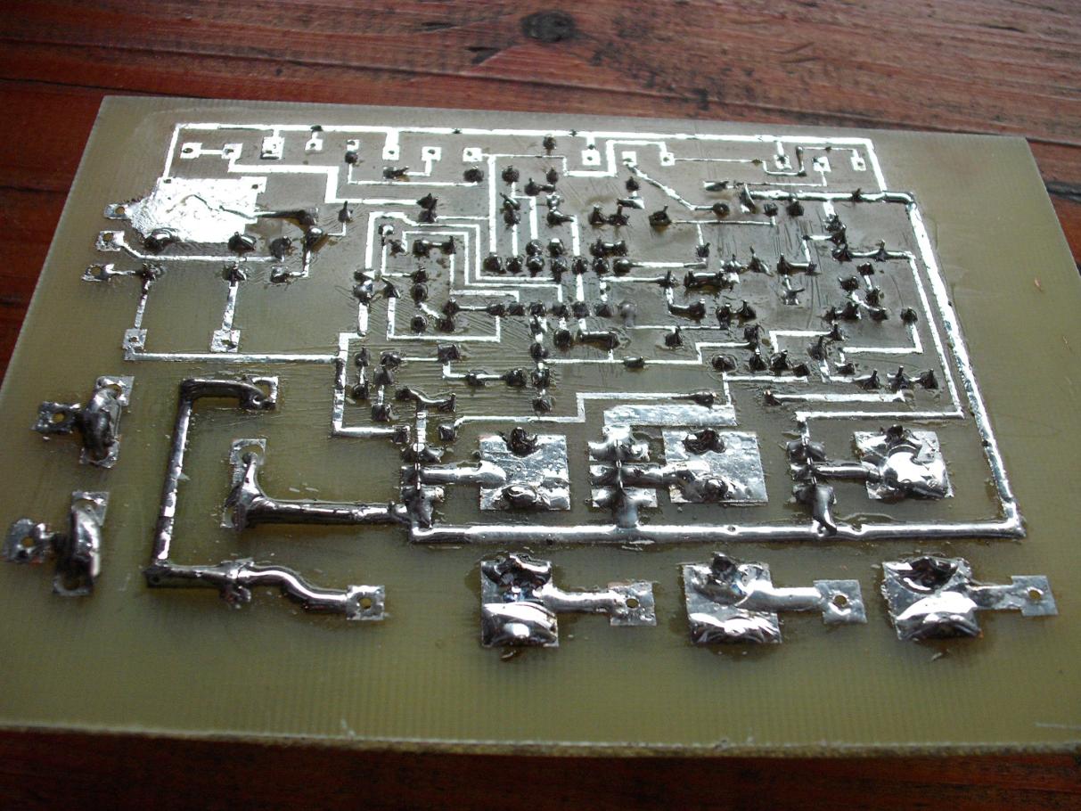
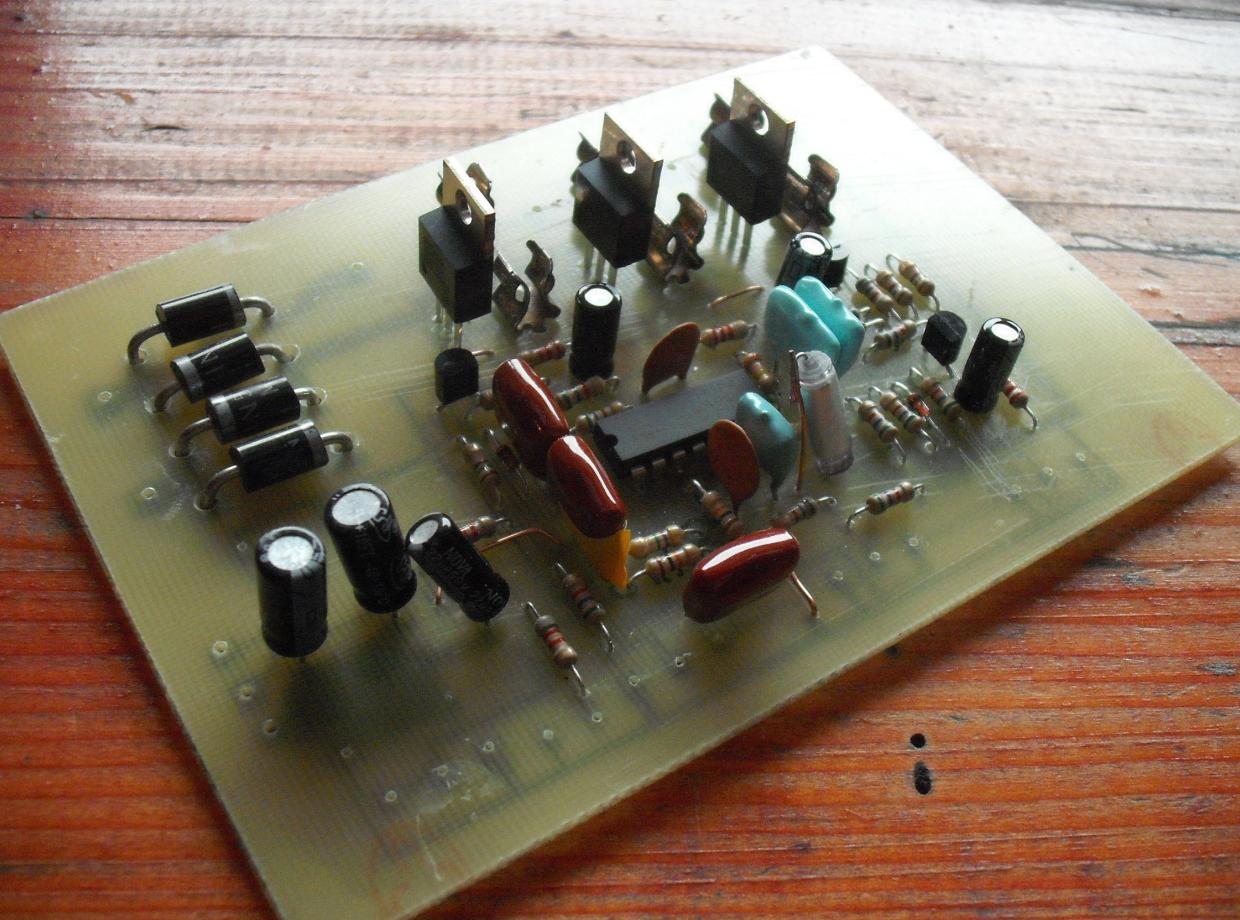
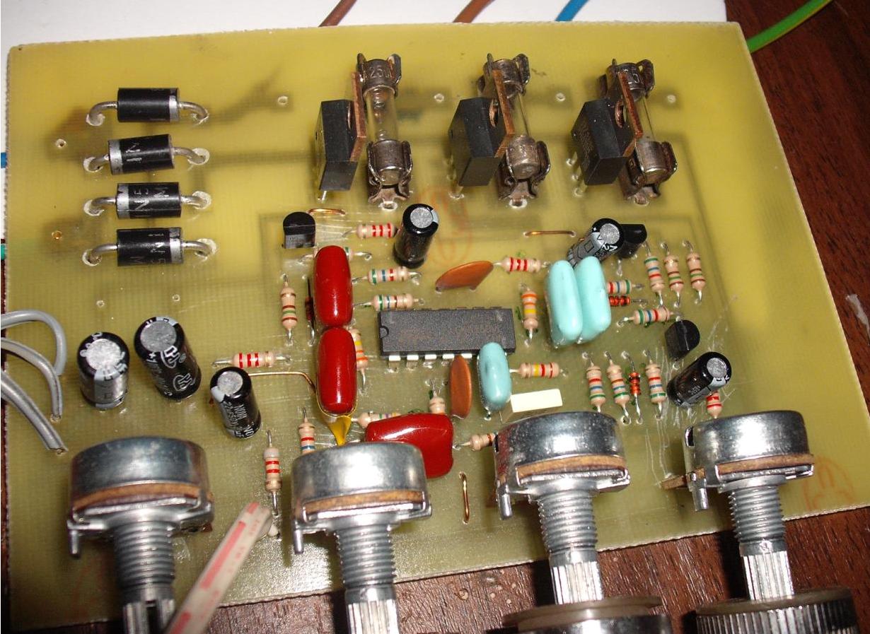
PCB:
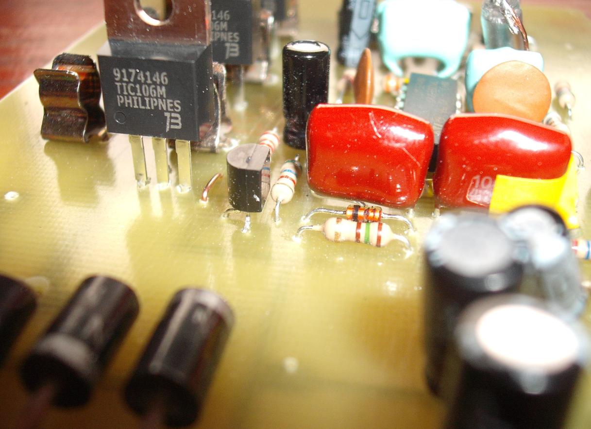
The board was made in thermal transfer method, digested in B327 and tinned. Digested paths despite being tinned, were additionally protected with rosin and acetone solution. MKT was used instead of 3,3nF MKSE capacitor.
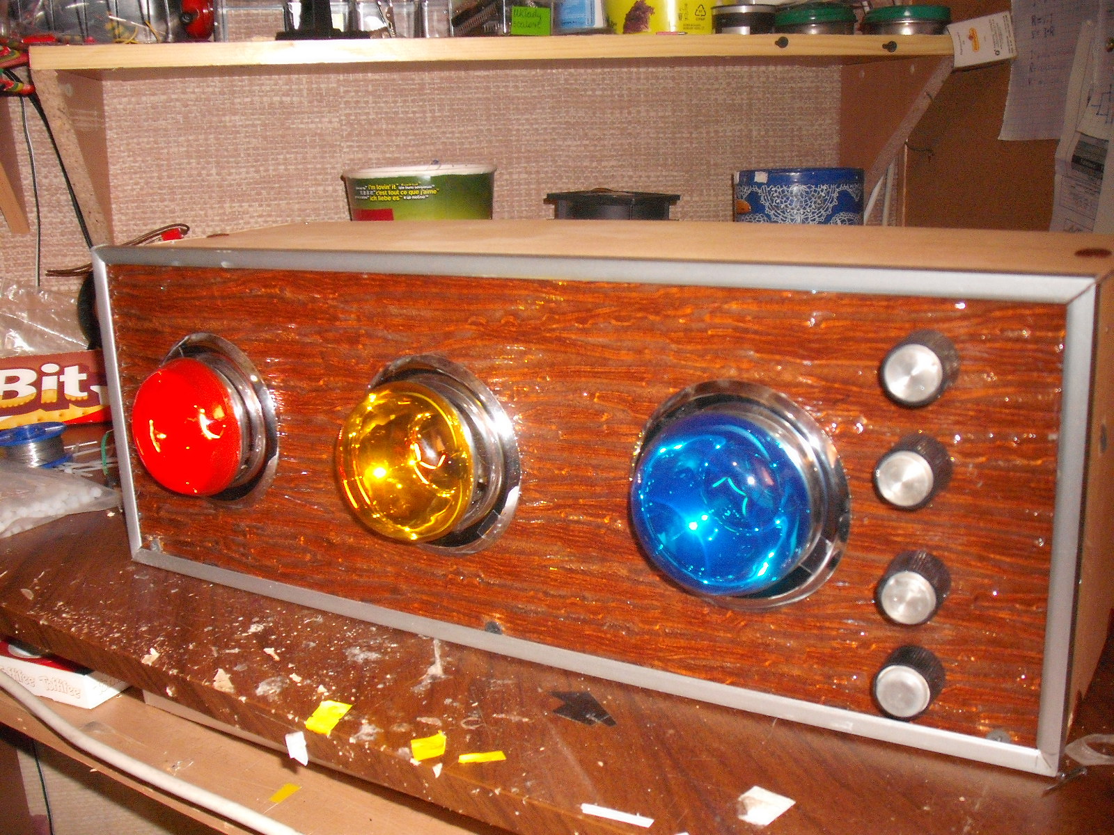
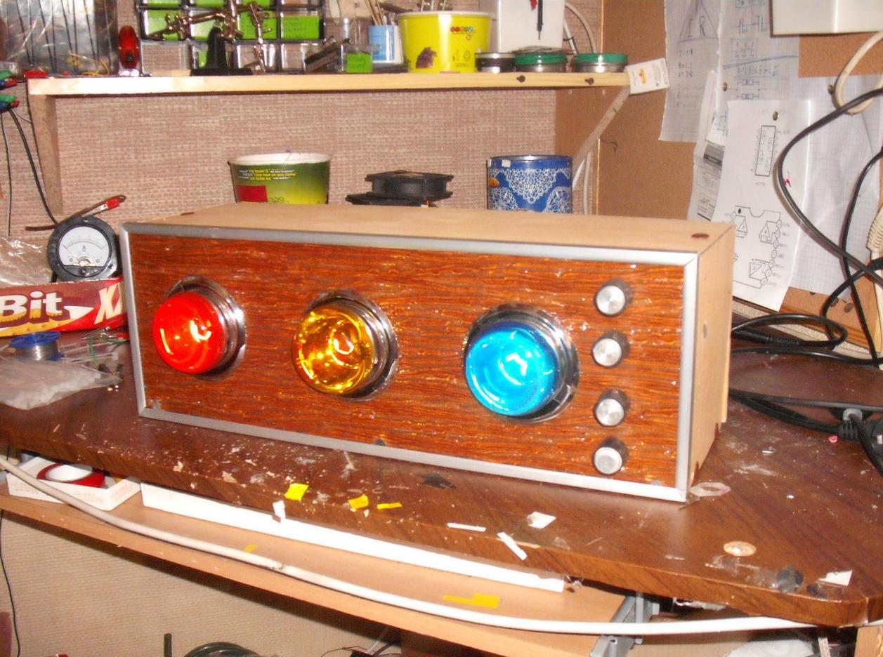
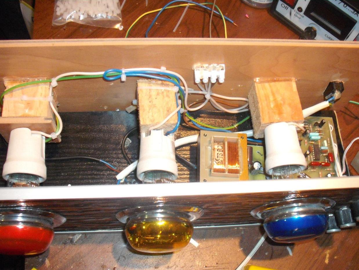
Bulbs:
Bulbs used are colourful bulbs with reflectors. Sockets and decorative frames can be bought together with bulbs.
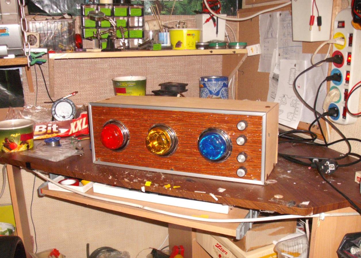
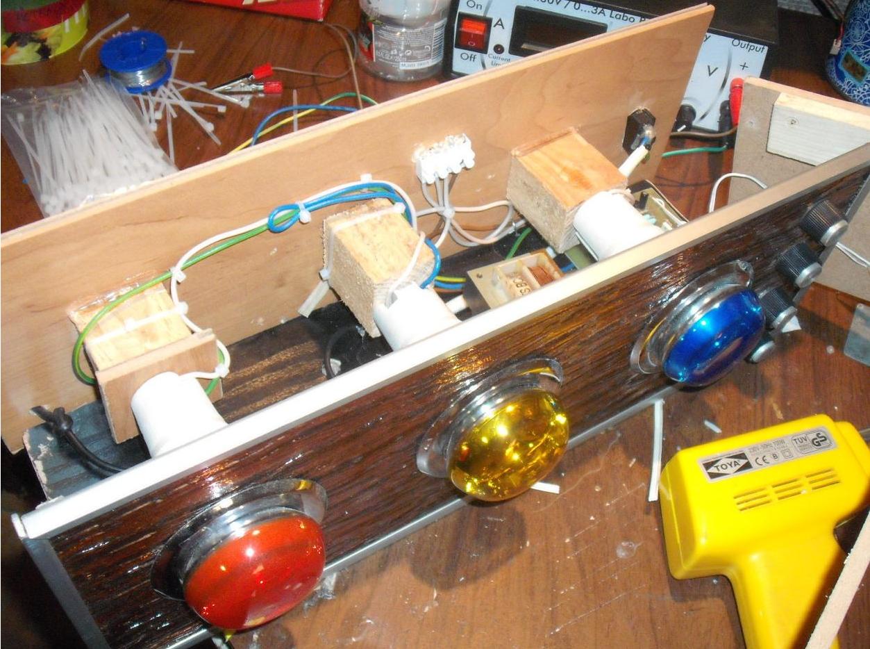
Housing:
Housing was made of wall panels. Front was made of brown plastic (plexiglass), framed on the corners by aluminum angles. Holes for bulbs were cut by jigsaw and silver frames were put into them.
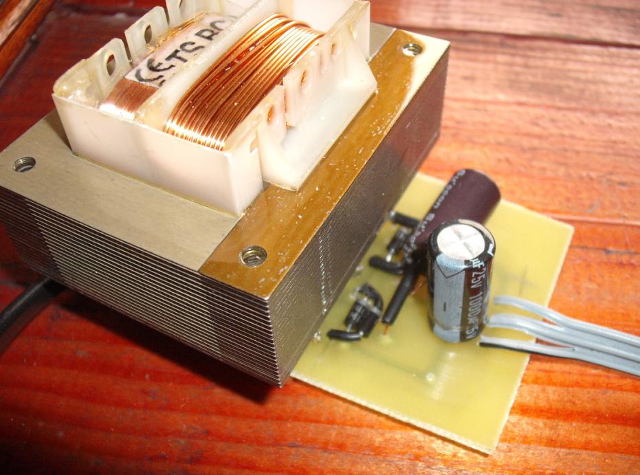
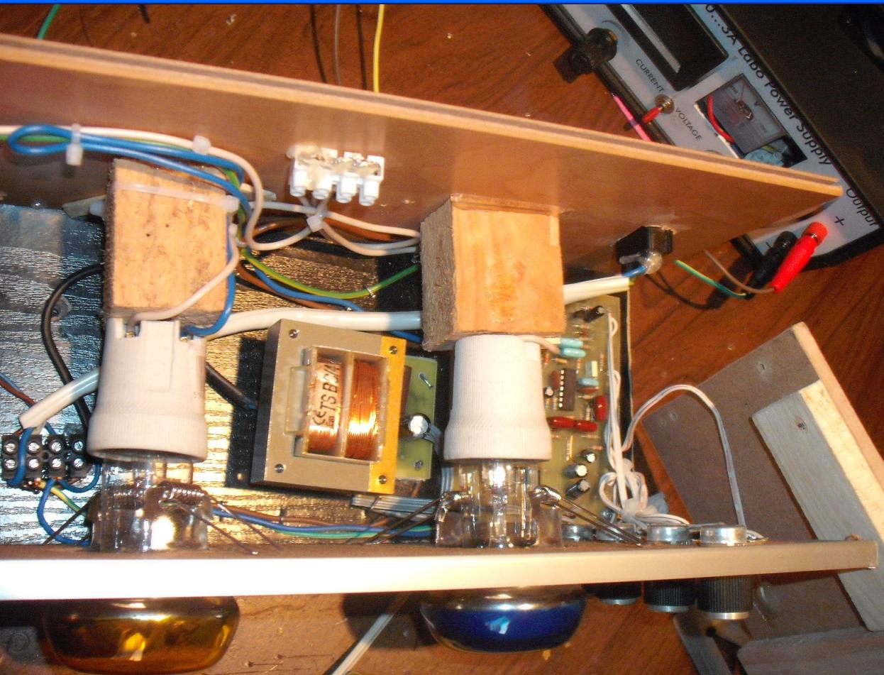
Mounting:
Power supply and colour-phone PCBs were mounted to the base of housing and supported by wooden pads. Frames of the bulbs were mounted to the wooden blocks, which were screwed to the rear wall of the housing. Cables that connect the driver board with the bulbs and power supply, are ordinary cables with diameter of about 2-3mm.
Pictures:
Link to original thread (useful attachment) – Mój kolorofon na J-050.