Continue to Site

Welcome to EDAboard.com

Welcome to our site! EDAboard.com is an international Electronics Discussion Forum focused on EDA software, circuits, schematics, books, theory, papers, asic, pld, 8051, DSP, Network, RF, Analog Design, PCB, Service Manuals... and a whole lot more! To participate you need to register. Registration is free. Click here to register now.

code for water flow sensor

Status
Not open for further replies.

hieuabcdefgh

Newbie level 5
Newbie level 5
Joined
Oct 16, 2020
Messages
8
Helped
0
Reputation
0
Reaction score
0
Trophy points
1
Activity points
48
I want to measure water flow with PIC 16f877a and display it on the LCD screen with my sensor liter per minute unit YF-S201 DN15. Help me...

[Moderator action: Above text is translated from original message below. Messages in language other than English are liable to be deleted.]

Tôi muốn đo lưu lượng nước bằng PIC 16f877a và hiển thị nó lên màn hình LCD với đơn vị lít / phút cảm biến của tôi là YF-S201 DN15. giúp tôi...
 
Last edited by a moderator:

Hi,

Nobody wants to write the code for you.
Show your code and we will try to correct it.

Indeed it's a quite simple task:
* measure the "time between two pulses"
* calculate frequency (may be omitted)
* calculate the flow according the table in the sensor's datasheet.

Klaus
 

[Moderator action: Above text is translated from original message. Messages in language other than English are liable to be deleted.]

This code I found on the Internet but when running the program does not work

Code:
#include "float2ascii.h"


// Kết nối mô-đun LCD

sbit LCD_RS tại LATC0_bit;

sbit LCD_EN tại LATC1_bit;

sbit LCD_D4 tại LATC2_bit;

sbit LCD_D5 tại LATC3_bit;

sbit LCD_D6 tại LATC4_bit;

sbit LCD_D7 tại LATC5_bit;


sbit LCD_RS_Direction tại TRISC0_bit;

sbit LCD_EN_Direction tại TRISC1_bit;

sbit LCD_D4_Direction tại TRISC2_bit;

sbit LCD_D5_Direction tại TRISC3_bit;

sbit LCD_D6_Direction tại TRISC4_bit;

sbit LCD_D7_Direction tại TRISC5_bit;

// Kết thúc kết nối mô-đun LCD


số ký tự = 0;

bộ đếm dài không dấu = 0;

gấp đôi lítPerSec = 0, lítFlowed, lítPerMinute = 0, lítPerHour = 0, xungPerSec = 0;

char str [30];


// Timer1

// Bộ lưu trữ 1: 8; TMR1 Tải trước = 3036; Thời gian ngắt thực tế: 500 ms


// Đặt / Sao chép phần này vào phần khai báo

void InitTimer1 () {

    T1CON = 0x31;

    TMR1IF_bit = 0;

    TMR1H = 0x0B;

    TMR1L = 0xDC;

    TMR1IE_bit = 1;

    INTCON = 0xC0;

}


void ngắt () {

    nếu (INT0IF_bit) {

         if (TMR1ON_bit == 0) {

              TMR1ON_bit = 1;           

         }

         khác bộ đếm + = 1;


         INT0IF_bit = 0;

    }


    nếu (TMR1IF_bit) {

        TMR1IF_bit = 0;

        TMR1H = 0x0B;

        TMR1L = 0xDC;

        //Nhập mã của bạn ở đây

        if (++ count == 2) {

             INT0IE_bit = 0;

             TMR1ON_bit = 0;           

             đếm = 0;                                         

        }       

    }

}


void main () {


    CM1CON0 = 0x00;

    CM2CON0 = 0x00;


    SLRCON = 0x00;


    ANSELA = 0x00;

    ANSELB = 0x00;

    ANSELC = 0x00;


    TRISA = 0xC0;

    TRISB = 0x01;

    TRISC = 0x00;


    CỔNG = 0x00;

    PORTB = 0x00;

    PORTC = 0x00;


    LCD_Init ();                     

    LCD_Cmd (_LCD_CURSOR_OFF);

    LCD_Cmd (_LCD_CLEAR);           


    LCD_Out (1,6, "Đồng hồ đo lưu lượng");


    INTEDG0_bit = 1;

    INT0IE_bit = 1;

    PEIE_bit = 1;

    GIE_bit = 1;


    INT0IF_bit = 0;


    InitTimer1 ();


    trong khi (1) {   


        trong khi (TMR1ON_bit);


        // bộ đếm * 60 / 7,5 = tốc độ dòng chảy tính bằng L / giờ


        bộ đếm xungPerSec = (kép);

        lítPerHour = xungPerSec * 60 / 7,5;

        lítPerMinute = lítPerHour / 60;


        Float2Ascii (lítPerMinute, str, 2);

        strcat (str, "Ltr / phút");

        LCD_Out (1,1, str);


        Float2Ascii (lítPerHour, str, 2);

        strcat (str, "Ltr / hr");

        LCD_Out (2,1, str);


        InitTimer1 ();

        bộ đếm = 0;

        INT0IE_bit = 1;

    }

}
 
Last edited by a moderator:

Hello,

Doesn't works means ????
No message on LCD ?
add a led blinking in main loop to see if the program is running ..

in your code , use english names for variables as
"char, byte ,int ,unsigned int ..." used on C langage !
and comments in english..

after, maybe you can get some help
 

this is my code but the output is not worth someone please help me

Code:
#include "float2ascii.h"


// LCD module connections

sbit LCD_RS at LATC0_bit;

sbit LCD_EN at LATC1_bit;

sbit LCD_D4 at LATC2_bit;

sbit LCD_D5 at LATC3_bit;

sbit LCD_D6 at LATC4_bit;

sbit LCD_D7 at LATC5_bit;


sbit LCD_RS_Direction at TRISC0_bit;

sbit LCD_EN_Direction at TRISC1_bit;

sbit LCD_D4_Direction at TRISC2_bit;

sbit LCD_D5_Direction at TRISC3_bit;

sbit LCD_D6_Direction at TRISC4_bit;

sbit LCD_D7_Direction at TRISC5_bit;

// End LCD module connections


char count = 0;

unsigned long counter = 0;

double litersPerSec = 0, litersFlowed, litersPerMinute = 0, litersPerHour = 0, pulsePerSec = 0;

char str[30];


//Timer1

//Prescaler 1:8; TMR1 Preload = 3036; Actual Interrupt Time : 500 ms


//Place/Copy this part in declaration section

void InitTimer1(){

    T1CON = 0x31;

    TMR1IF_bit = 0;

    TMR1H = 0x0B;

    TMR1L = 0xDC;

    TMR1IE_bit = 1;

    INTCON = 0xC0;

}


void interrupt() {

    if(INT0IF_bit) {

         if(TMR1ON_bit == 0) {

              TMR1ON_bit = 1;             

         }

         else counter += 1;


         INT0IF_bit = 0;

    }


    if(TMR1IF_bit){

        TMR1IF_bit = 0;

        TMR1H = 0x0B;

        TMR1L = 0xDC;

        //Enter your code here

        if(++count == 2) {

             INT0IE_bit = 0;

             TMR1ON_bit = 0;             

             count = 0;                                           

        }         

    }

}


void main() {


    CM1CON0 = 0x00;

    CM2CON0 = 0x00;


    SLRCON = 0x00;


    ANSELA = 0x00;

    ANSELB = 0x00;

    ANSELC = 0x00;


    TRISA = 0xC0;

    TRISB = 0x01;

    TRISC = 0x00;


    PORTA = 0x00;

    PORTB = 0x00;

    PORTC = 0x00;


    LCD_Init();                       

    LCD_Cmd(_LCD_CURSOR_OFF);

    LCD_Cmd(_LCD_CLEAR);             


    LCD_Out(1,6,"Flow Meter");


    INTEDG0_bit = 1;

    INT0IE_bit = 1;

    PEIE_bit = 1;

    GIE_bit = 1;


    INT0IF_bit = 0;


    InitTimer1();


    while(1) {     


        while(TMR1ON_bit);


        //counter * 60 / 7.5 = flow rate in L/hr


        pulsePerSec = (double)counter;

        litersPerHour = pulsePerSec * 60 / 7.5;

        litersPerMinute =  litersPerHour / 60;


        Float2Ascii(litersPerMinute, str, 2);

        strcat(str, " Ltr/min");

        LCD_Out(1,1,str);


        Float2Ascii(litersPerHour, str, 2);

        strcat(str, " Ltr/hr");

        LCD_Out(2,1,str);


        InitTimer1();

        counter = 0;

        INT0IE_bit = 1;

    }

}
 
Last edited by a moderator:

hello,

your code is nearly good ..
i tested on a 16F877 ( not 877A !) at 8MHz (not 4MHz !)
with a TTL signal generator to simulate the Flow sensor
so Timer1 =250mS => count=4 to get 1sec
I also used a terminal instead of a LCD ...
i did not find out "INTIE_bit" in mikroC ??? so used " INTCON.B4" instead .

Test t is OK

Maybe with Pulse width measurement , (Capture mode) you can get a better resolution and accuracy
for LOW flow troughput .. it depends of what is your measure range .. ?
Accuracy increase with the frequency value !
it is up to you !

the code (y) ( between code balises ! )

Code:
#define CR 13
#define LF 10
#define TAB 9

#define FOSC "Q 8MHz"

const char * mesg1="16F877 ADC UART  Q=8Mhz";
const char * mesg2="Test sur Breadboard 16F877";
const char * mesg3=" ....";

char txt[64];
int i,j,k;

char count = 0;
unsigned long counter = 0;
float  litersPerSec = 0, litersFlowed, litersPerMinute = 0, litersPerHour = 0, pulsePerSec = 0;
char str[30];

//Timer1
//Prescaler 1:8; TMR1 Preload = 3036; Actual Interrupt Time : 500 ms  at 4MHz
// 250mS at 8Mhz
//Place/Copy this part in declaration section
void InitTimer1()
{
T1CON = 0x31;
TMR1IF_bit = 0;
TMR1H = 0x0B;
TMR1L = 0xDC;
TMR1IE_bit = 1;
INTCON = 0xC0;
}

void Interrupts() iv 0x0004 ics ICS_AUTO
{
if(INTCON.INTF==1)
{
    if(TMR1ON_bit == 0)
    {
     TMR1ON_bit = 1;
    }
   else
     counter ++;
INTF_bit = 0;
}
if(TMR1IF_bit)
{
TMR1IF_bit = 0;
TMR1H = 0x0B;
TMR1L = 0xDC;
//Enter your code here
if(++count == 4)
{
   INTCON.B4=0 ; // INTIE_bit = 0;
   TMR1ON_bit = 0;
   count = 0;
}
}
}

void Float2Ascii (float x, unsigned char *str,char precision)
{
// converts a floating point number to an ascii string
// version limitée à 5 decimales maximum
// x is stored into str, which should be at least 30 chars long
int ie, i, k, ndig;
double y;
if (precision>=5) precision=5;  else precision++;
ndig =   precision;

ie = 0;
// if x negative, write minus and reverse
if ( x < 0.00000)
{
   *str++ = '-';
   x = -x;
}
// put x in range 1 <= x < 10
if (x > 0.000000) while (x < 1.000000)
{
   x *= 10.000;                // a la place de =*
   ie--;
}
while (x >= 10.0000)
{
   x = x/10.0000;
   ie++;
}
// in f format, number of digits is related to size
ndig += ie;                                // a la place de =+
//round. x is between 1 and 10 and ndig will be printed to
// right of decimal point so rounding is ...
for (y = i = 1; i < ndig; i++)
y = y/10.0000;
x += y/2.0000;
if (x >= 10.0000) {x = 1.0000; ie++;}
if (ie<0)
{
   *str++ = '0'; *str++ = '.';
   if (ndig < 0) ie = ie-ndig;
   for (i = -1; i > ie; i--)  *str++ = '0';
}
for (i=0; i < ndig; i++)
{
   k = x;
   *str++ = k + '0';
   if (i ==  ie ) *str++ = '.';
   x -= (y=k);
   x *= 10.0000;
  }
*str = '\0';
}


// --- Copie le texte depuis ROM vers RAM
void strConstRamCpy(char *dest, const char *source) {
  while(*source) *dest++ = *source++ ;
  *dest = 0 ;    // terminateur
}

CPrint(const char * tx)
{
while (* tx)
    UART1_Write(* tx++);
}

Print(char * texte)
{
while (* texte)
    UART1_Write(* texte++);
}

void CRLF()
{
  UART1_Write(CR);
  UART1_Write(LF);
  }

void main()
{


TRISA = 0xC0;
TRISB = 0x01;
TRISC = 0x00;

PORTA = 0x00;
PORTB = 0x00;
PORTC = 0x00;


UART1_Init(19200);              // initialize UART1 module
Delay_ms(100);
CRLF();
strConstRamCpy(txt,mesg1); Print(txt); CRLF();
strConstRamCpy(txt,mesg2); Print(txt); CRLF();
strConstRamCpy(txt,mesg3); Print(txt); CRLF();
CRLF();
Delay_ms(1000);


INTEDG_bit = 1;
INTCON.B4 = 1;
INTF_bit = 0;
InitTimer1();
PEIE_bit = 1;
GIE_bit = 1;

CPrint(" Flow Meter simulation  by using this generator : \r\n");
CPrint(" http://paulfjujo.free.fr/OLDIES/images/Generateur-Quartz_4040_2011.jpg\r\n");

while(1)
{
  while(TMR1ON_bit);
  CPrint(" Pulse Frequency in Hz :");
  //counter * 60 / 7.5 = flow rate in L/hr
  LongToStr(counter,str);
  Print(str);
  UART1_Write(TAB);
  pulsePerSec = (float)counter;
  litersPerMinute= pulsePerSec/7.5;
  litersPerHour = litersPerMinute * 60.0 ;
  Float2Ascii(litersPerMinute, str, 2);
  strcat(str, " Ltr/min");
  Print(str);
  UART1_Write(TAB);
  Float2Ascii(litersPerHour, str, 2);
  strcat(str, " Ltr/hr");
  Print(str);
  CRLF();
  InitTimer1();
  counter = 0;
  INTCON.B4=1; // INT0IE_bit = 1;
  PORTA.B4=!PORTA.B4;   // led clignote
}
}

Results

(17:40:45.387)
(17:40:45.421) 16F877 ADC UART Q=8Mhz
(17:40:45.421) Test sur Breadboard 16F877
(17:40:45.421) ....
(17:40:45.421)
(17:40:46.420) Flow Meter simulation by using this generator :
(17:40:46.447) **broken link removed**
(17:40:47.419) Pulse Frequency in Hz : 4 0.53 Ltr/min 32.00 Ltr/hr
(17:40:48.461) Pulse Frequency in Hz : 5 0.67 Ltr/min 40.00 Ltr/hr
(17:40:49.501) Pulse Frequency in Hz : 5 0.67 Ltr/min 40.00 Ltr/hr
(17:40:50.540) Pulse Frequency in Hz : 5 0.67 Ltr/min 40.00 Ltr/hr
(17:40:51.580) Pulse Frequency in Hz : 5 0.67 Ltr/min 40.00 Ltr/hr
(17:40:52.619) Pulse Frequency in Hz : 5 0.67 Ltr/min 40.00 Ltr/hr
(17:40:53.660) Pulse Frequency in Hz : 8 1.07 Ltr/min 64.00 Ltr/hr
(17:40:54.700) Pulse Frequency in Hz : 9 1.20 Ltr/min 72.00 Ltr/hr
(17:40:55.742) Pulse Frequency in Hz : 10 1.33 Ltr/min 80.00 Ltr/hr
(17:40:56.783) Pulse Frequency in Hz : 10 1.33 Ltr/min 80.00 Ltr/hr
(17:40:57.824) Pulse Frequency in Hz : 10 1.33 Ltr/min 80.00 Ltr/hr
(17:40:58.866) Pulse Frequency in Hz : 10 1.33 Ltr/min 80.00 Ltr/hr
(17:40:59.907) Pulse Frequency in Hz : 9 1.20 Ltr/min 72.00 Ltr/hr
(17:41:00.948) Pulse Frequency in Hz : 9 1.20 Ltr/min 72.00 Ltr/hr
(17:41:01.988) Pulse Frequency in Hz : 10 1.33 Ltr/min 80.00 Ltr/hr
(17:41:03.031) Pulse Frequency in Hz : 10 1.33 Ltr/min 80.00 Ltr/hr
(17:41:04.072) Pulse Frequency in Hz : 19 2.53 Ltr/min 152.00 Ltr/hr
(17:41:05.116) Pulse Frequency in Hz : 19 2.53 Ltr/min 152.00 Ltr/hr
(17:41:06.159) Pulse Frequency in Hz : 20 2.67 Ltr/min 160.00 Ltr/hr
(17:41:07.203) Pulse Frequency in Hz : 19 2.53 Ltr/min 152.00 Ltr/hr
(17:41:08.247) Pulse Frequency in Hz : 20 2.67 Ltr/min 160.00 Ltr/hr
(17:41:09.290) Pulse Frequency in Hz : 20 2.67 Ltr/min 160.00 Ltr/hr
(17:41:10.333) Pulse Frequency in Hz : 19 2.53 Ltr/min 152.00 Ltr/hr
(17:41:11.378) Pulse Frequency in Hz : 20 2.67 Ltr/min 160.00 Ltr/hr
(17:41:12.420) Pulse Frequency in Hz : 19 2.53 Ltr/min 152.00 Ltr/hr
(17:41:13.465) Pulse Frequency in Hz : 24 3.20 Ltr/min 192.00 Ltr/hr
(17:41:14.508) Pulse Frequency in Hz : 39 5.20 Ltr/min 312.00 Ltr/hr
(17:41:15.552) Pulse Frequency in Hz : 39 5.20 Ltr/min 312.00 Ltr/hr
(17:41:16.596) Pulse Frequency in Hz : 39 5.20 Ltr/min 312.00 Ltr/hr
(17:41:17.639) Pulse Frequency in Hz : 39 5.20 Ltr/min 312.00 Ltr/hr
(17:41:18.683) Pulse Frequency in Hz : 39 5.20 Ltr/min 312.00 Ltr/hr
(17:41:19.727) Pulse Frequency in Hz : 39 5.20 Ltr/min 312.00 Ltr/hr
(17:41:20.771) Pulse Frequency in Hz : 39 5.20 Ltr/min 312.00 Ltr/hr
(17:41:21.814) Pulse Frequency in Hz : 69 9.20 Ltr/min 552.00 Ltr/hr
(17:41:22.858) Pulse Frequency in Hz : 78 10.40 Ltr/min 624.00 Ltr/hr
(17:41:23.903) Pulse Frequency in Hz : 78 10.40 Ltr/min 624.00 Ltr/hr
(17:41:24.948) Pulse Frequency in Hz : 78 10.40 Ltr/min 624.00 Ltr/hr
(17:41:25.996) Pulse Frequency in Hz : 78 10.40 Ltr/min 624.00 Ltr/hr
(17:41:27.040) Pulse Frequency in Hz : 78 10.40 Ltr/min 624.00 Ltr/hr
(17:41:28.086) Pulse Frequency in Hz : 78 10.40 Ltr/min 624.00 Ltr/hr
(17:41:29.131) Pulse Frequency in Hz : 120 16.00 Ltr/min 960.00 Ltr/hr
(17:41:30.177) Pulse Frequency in Hz : 156 20.80 Ltr/min 1248.00 Ltr/hr
(17:41:31.227) Pulse Frequency in Hz : 156 20.80 Ltr/min 1248.00 Ltr/hr
(17:41:32.275) Pulse Frequency in Hz : 156 20.80 Ltr/min 1248.00 Ltr/hr
(17:41:33.324) Pulse Frequency in Hz : 157 20.93 Ltr/min 1256.00 Ltr/hr
(17:41:34.372) Pulse Frequency in Hz : 157 20.93 Ltr/min 1256.00 Ltr/hr
(17:41:35.421) Pulse Frequency in Hz : 156 20.80 Ltr/min 1248.00 Ltr/hr
(17:41:36.469) Pulse Frequency in Hz : 156 20.80 Ltr/min 1248.00 Ltr/hr
(17:41:37.518) Pulse Frequency in Hz : 156 20.80 Ltr/min 1248.00 Ltr/hr
(17:41:38.566) Pulse Frequency in Hz : 156 20.80 Ltr/min 1248.00 Ltr/hr
 

hello,

your code is nearly good ..
i tested on a 16F877 ( not 877A !) at 8MHz (not 4MHz !)
with a TTL signal generator to simulate the Flow sensor
so Timer1 =250mS => count=4 to get 1sec
I also used a terminal instead of a LCD ...
i did not find out "INTIE_bit" in mikroC ??? so used " INTCON.B4" instead .

Test t is OK

Maybe with Pulse width measurement , (Capture mode) you can get a better resolution and accuracy
for LOW flow troughput .. it depends of what is your measure range .. ?
Accuracy increase with the frequency value !
it is up to you !

the code (y) ( between code balises ! )

Code:
#define CR 13
#define LF 10
#define TAB 9

#define FOSC "Q 8MHz"

const char * mesg1="16F877 ADC UART  Q=8Mhz";
const char * mesg2="Test sur Breadboard 16F877";
const char * mesg3=" ....";

char txt[64];
int i,j,k;

char count = 0;
unsigned long counter = 0;
float  litersPerSec = 0, litersFlowed, litersPerMinute = 0, litersPerHour = 0, pulsePerSec = 0;
char str[30];

//Timer1
//Prescaler 1:8; TMR1 Preload = 3036; Actual Interrupt Time : 500 ms  at 4MHz
// 250mS at 8Mhz
//Place/Copy this part in declaration section
void InitTimer1()
{
T1CON = 0x31;
TMR1IF_bit = 0;
TMR1H = 0x0B;
TMR1L = 0xDC;
TMR1IE_bit = 1;
INTCON = 0xC0;
}

void Interrupts() iv 0x0004 ics ICS_AUTO
{
if(INTCON.INTF==1)
{
    if(TMR1ON_bit == 0)
    {
     TMR1ON_bit = 1;
    }
   else
     counter ++;
INTF_bit = 0;
}
if(TMR1IF_bit)
{
TMR1IF_bit = 0;
TMR1H = 0x0B;
TMR1L = 0xDC;
//Enter your code here
if(++count == 4)
{
   INTCON.B4=0 ; // INTIE_bit = 0;
   TMR1ON_bit = 0;
   count = 0;
}
}
}

void Float2Ascii (float x, unsigned char *str,char precision)
{
// converts a floating point number to an ascii string
// version limitée à 5 decimales maximum
// x is stored into str, which should be at least 30 chars long
int ie, i, k, ndig;
double y;
if (precision>=5) precision=5;  else precision++;
ndig =   precision;

ie = 0;
// if x negative, write minus and reverse
if ( x < 0.00000)
{
   *str++ = '-';
   x = -x;
}
// put x in range 1 <= x < 10
if (x > 0.000000) while (x < 1.000000)
{
   x *= 10.000;                // a la place de =*
   ie--;
}
while (x >= 10.0000)
{
   x = x/10.0000;
   ie++;
}
// in f format, number of digits is related to size
ndig += ie;                                // a la place de =+
//round. x is between 1 and 10 and ndig will be printed to
// right of decimal point so rounding is ...
for (y = i = 1; i < ndig; i++)
y = y/10.0000;
x += y/2.0000;
if (x >= 10.0000) {x = 1.0000; ie++;}
if (ie<0)
{
   *str++ = '0'; *str++ = '.';
   if (ndig < 0) ie = ie-ndig;
   for (i = -1; i > ie; i--)  *str++ = '0';
}
for (i=0; i < ndig; i++)
{
   k = x;
   *str++ = k + '0';
   if (i ==  ie ) *str++ = '.';
   x -= (y=k);
   x *= 10.0000;
  }
*str = '\0';
}


// --- Copie le texte depuis ROM vers RAM
void strConstRamCpy(char *dest, const char *source) {
  while(*source) *dest++ = *source++ ;
  *dest = 0 ;    // terminateur
}

CPrint(const char * tx)
{
while (* tx)
    UART1_Write(* tx++);
}

Print(char * texte)
{
while (* texte)
    UART1_Write(* texte++);
}

void CRLF()
{
  UART1_Write(CR);
  UART1_Write(LF);
  }

void main()
{


TRISA = 0xC0;
TRISB = 0x01;
TRISC = 0x00;

PORTA = 0x00;
PORTB = 0x00;
PORTC = 0x00;


UART1_Init(19200);              // initialize UART1 module
Delay_ms(100);
CRLF();
strConstRamCpy(txt,mesg1); Print(txt); CRLF();
strConstRamCpy(txt,mesg2); Print(txt); CRLF();
strConstRamCpy(txt,mesg3); Print(txt); CRLF();
CRLF();
Delay_ms(1000);


INTEDG_bit = 1;
INTCON.B4 = 1;
INTF_bit = 0;
InitTimer1();
PEIE_bit = 1;
GIE_bit = 1;

CPrint(" Flow Meter simulation  by using this generator : \r\n");
CPrint(" http://paulfjujo.free.fr/OLDIES/images/Generateur-Quartz_4040_2011.jpg\r\n");

while(1)
{
  while(TMR1ON_bit);
  CPrint(" Pulse Frequency in Hz :");
  //counter * 60 / 7.5 = flow rate in L/hr
  LongToStr(counter,str);
  Print(str);
  UART1_Write(TAB);
  pulsePerSec = (float)counter;
  litersPerMinute= pulsePerSec/7.5;
  litersPerHour = litersPerMinute * 60.0 ;
  Float2Ascii(litersPerMinute, str, 2);
  strcat(str, " Ltr/min");
  Print(str);
  UART1_Write(TAB);
  Float2Ascii(litersPerHour, str, 2);
  strcat(str, " Ltr/hr");
  Print(str);
  CRLF();
  InitTimer1();
  counter = 0;
  INTCON.B4=1; // INT0IE_bit = 1;
  PORTA.B4=!PORTA.B4;   // led clignote
}
}

Results
Thank you. But I don't understand how to simulate a flow meter. How to draw it all out and connect to the pin of the PIC 16f877
 

Thank you. But I don't understand how to simulate a flow meter. How to draw it all out and connect to the pin of the PIC 16f877

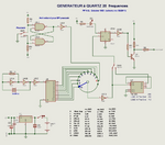
did you see the picture <-- click here !
FGen.png
[moderator action: uploaded file from external file server]

the "TTL output" signal is just connected to "RB0 MCU input"
and also "Gnd" must be connected together !

Check if you can add a PWM output ( so, with a know frequency value),
and use this output as "flow sensor "information
or another timer ...

maybe, just touching by hand, RB0 input, is enough to enter 50Hz (or 60Hz) signal ,
but not recommended at all.
 
Last edited by a moderator:

Hi,
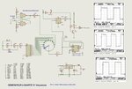
did you see**broken link removed** <-- click here !
The schematic has a lot of issuses:
* Some minor mistakes like missing or useless junction dots ... or signal flow from right to left...
* an unusal XTAL oscillator circuit (Does it even work this way?)
* using non existing 400kHz XTAL
* driving standard CMOS ( I guess without dedicated naming it is CD4040, CD4049..) from non compatible "LS" logic signals
* nonsense LED connection to a "D" input of a Flip Flop...

I doubt this circuit can work this way. At least it is not useful to teach newbies.

Klaus
 

Hello,


The schematic has a lot of issuses:
* Some minor mistakes like missing or useless junction dots ... or signal flow from right to left...

???
a point is used to show the connection between wires.. no point means no connection
signal goes from left to right.. as usual in all schematics

* an unusal XTAL oscillator circuit (Does it even work this way?)
* using non existing 400kHz XTAL

You can't say that.. in fact, you don't know that this kind of quartz could be exist !
it is a big size of quartz, with value 400.000 khz ,
it was used before inside a ROCHAR Frequencmeter (in year 1970)

* driving standard CMOS ( I guess without dedicated naming it is CD4040, CD4049..) from non compatible "LS" logic signals
Even with different technology, it works fine with 4.5V to 5V powersupply
and the frequency domain is enough LOW ..to avoid problems.

* nonsense LED connection to a "D" input of a Flip Flop...

You are right on this point
Mistake when porting old drawing 1989 made with paint , to ISIS drawing in 2011
Led is connected to the ouput of last buffer CD4049.
and Q pin of 74LS74 to VCC

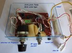
i use this old hardware generator in many cases .
Even , if now, DDS generator with PIC MCU is a better way.
 

Attachments

  • Generateur-Quartz_4040_2020_.jpg
    Generateur-Quartz_4040_2020_.jpg
    160.9 KB · Views: 129
  • Gene1989_boite.jpg
    Gene1989_boite.jpg
    160.3 KB · Views: 136

Hi,
I refer to the schematic given in
???
a point is used to show the connection between wires.. no point means no connection
signal goes from left to right.. as usual in all schematics
* U7_pin3 missing junction
* two useless junction dots around R5
* signal flow around 7805 from right to left

You can't say that.. in fact, you don't know that this kind of quartz could be exist !
it is a big size of quartz, with value 400.000 khz ,
it was used before inside a ROCHAR Frequencmeter (in year 1970)
Maybe in the 1970ies, I don´t know. But now we are half a decade later. Farnell lists over 6000 XTALs, the next best is 307.2kHz (for about 18 Euros).
Maybe ther is a 400kHz one, but it seems not to be any standard nowadays.

Even with different technology, it works fine with 4.5V to 5V powersupply
and the frequency domain is enough LOW ..to avoid problems.
I don´t doubt that your circuit is working. But I call it "accidentlally", because CD4040 V_IH_min is 4V while LS74 V_OH_min is 2.4V only (3.4V typ).

Don´t get me wrong. A VW Käfer (the old Volkswagen Beetle) was a good car in the 1970ies, but thanks god there was a development in the past 50 years.
Some of the cars still are running and I like them - as you like your frequency generator. I think I understand.

Klaus
 

hello,

your code is nearly good ..
i tested on a 16F877 ( not 877A !) at 8MHz (not 4MHz !)
with a TTL signal generator to simulate the Flow sensor
so Timer1 =250mS => count=4 to get 1sec
I also used a terminal instead of a LCD ...
i did not find out "INTIE_bit" in mikroC ??? so used " INTCON.B4" instead .

Test t is OK

Maybe with Pulse width measurement , (Capture mode) you can get a better resolution and accuracy
for LOW flow troughput .. it depends of what is your measure range .. ?
Accuracy increase with the frequency value !
it is up to you !

the code (y) ( between code balises ! )

Code:
#define CR 13
#define LF 10
#define TAB 9

#define FOSC "Q 8MHz"

const char * mesg1="16F877 ADC UART  Q=8Mhz";
const char * mesg2="Test sur Breadboard 16F877";
const char * mesg3=" ....";

char txt[64];
int i,j,k;

char count = 0;
unsigned long counter = 0;
float  litersPerSec = 0, litersFlowed, litersPerMinute = 0, litersPerHour = 0, pulsePerSec = 0;
char str[30];

//Timer1
//Prescaler 1:8; TMR1 Preload = 3036; Actual Interrupt Time : 500 ms  at 4MHz
// 250mS at 8Mhz
//Place/Copy this part in declaration section
void InitTimer1()
{
T1CON = 0x31;
TMR1IF_bit = 0;
TMR1H = 0x0B;
TMR1L = 0xDC;
TMR1IE_bit = 1;
INTCON = 0xC0;
}

void Interrupts() iv 0x0004 ics ICS_AUTO
{
if(INTCON.INTF==1)
{
    if(TMR1ON_bit == 0)
    {
     TMR1ON_bit = 1;
    }
   else
     counter ++;
INTF_bit = 0;
}
if(TMR1IF_bit)
{
TMR1IF_bit = 0;
TMR1H = 0x0B;
TMR1L = 0xDC;
//Enter your code here
if(++count == 4)
{
   INTCON.B4=0 ; // INTIE_bit = 0;
   TMR1ON_bit = 0;
   count = 0;
}
}
}

void Float2Ascii (float x, unsigned char *str,char precision)
{
// converts a floating point number to an ascii string
// version limitée à 5 decimales maximum
// x is stored into str, which should be at least 30 chars long
int ie, i, k, ndig;
double y;
if (precision>=5) precision=5;  else precision++;
ndig =   precision;

ie = 0;
// if x negative, write minus and reverse
if ( x < 0.00000)
{
   *str++ = '-';
   x = -x;
}
// put x in range 1 <= x < 10
if (x > 0.000000) while (x < 1.000000)
{
   x *= 10.000;                // a la place de =*
   ie--;
}
while (x >= 10.0000)
{
   x = x/10.0000;
   ie++;
}
// in f format, number of digits is related to size
ndig += ie;                                // a la place de =+
//round. x is between 1 and 10 and ndig will be printed to
// right of decimal point so rounding is ...
for (y = i = 1; i < ndig; i++)
y = y/10.0000;
x += y/2.0000;
if (x >= 10.0000) {x = 1.0000; ie++;}
if (ie<0)
{
   *str++ = '0'; *str++ = '.';
   if (ndig < 0) ie = ie-ndig;
   for (i = -1; i > ie; i--)  *str++ = '0';
}
for (i=0; i < ndig; i++)
{
   k = x;
   *str++ = k + '0';
   if (i ==  ie ) *str++ = '.';
   x -= (y=k);
   x *= 10.0000;
  }
*str = '\0';
}


// --- Copie le texte depuis ROM vers RAM
void strConstRamCpy(char *dest, const char *source) {
  while(*source) *dest++ = *source++ ;
  *dest = 0 ;    // terminateur
}

CPrint(const char * tx)
{
while (* tx)
    UART1_Write(* tx++);
}

Print(char * texte)
{
while (* texte)
    UART1_Write(* texte++);
}

void CRLF()
{
  UART1_Write(CR);
  UART1_Write(LF);
  }

void main()
{


TRISA = 0xC0;
TRISB = 0x01;
TRISC = 0x00;

PORTA = 0x00;
PORTB = 0x00;
PORTC = 0x00;


UART1_Init(19200);              // initialize UART1 module
Delay_ms(100);
CRLF();
strConstRamCpy(txt,mesg1); Print(txt); CRLF();
strConstRamCpy(txt,mesg2); Print(txt); CRLF();
strConstRamCpy(txt,mesg3); Print(txt); CRLF();
CRLF();
Delay_ms(1000);


INTEDG_bit = 1;
INTCON.B4 = 1;
INTF_bit = 0;
InitTimer1();
PEIE_bit = 1;
GIE_bit = 1;

CPrint(" Flow Meter simulation  by using this generator : \r\n");
CPrint(" http://paulfjujo.free.fr/OLDIES/images/Generateur-Quartz_4040_2011.jpg\r\n");

while(1)
{
  while(TMR1ON_bit);
  CPrint(" Pulse Frequency in Hz :");
  //counter * 60 / 7.5 = flow rate in L/hr
  LongToStr(counter,str);
  Print(str);
  UART1_Write(TAB);
  pulsePerSec = (float)counter;
  litersPerMinute= pulsePerSec/7.5;
  litersPerHour = litersPerMinute * 60.0 ;
  Float2Ascii(litersPerMinute, str, 2);
  strcat(str, " Ltr/min");
  Print(str);
  UART1_Write(TAB);
  Float2Ascii(litersPerHour, str, 2);
  strcat(str, " Ltr/hr");
  Print(str);
  CRLF();
  InitTimer1();
  counter = 0;
  INTCON.B4=1; // INT0IE_bit = 1;
  PORTA.B4=!PORTA.B4;   // led clignote
}
}

Results
sorry but your code doesn't work when i run it with error where #define FOSC "Q 8MHz" i don't know how but it looks like missing the library if possible can you send me the library file. thanks
 

hello,


find out the complete mikroC project in zip
there are no used external library apart from Mikroc lib
in this program

used lib :
Code:
_Lib_Math.mcl" "
_Lib_MathDouble.mcl" "
_Lib_System.mcl" "
_Lib_Delays.mcl" "
_Lib_CString.mcl" "
_Lib_Conversions.mcl" "
_Lib_ADC_A_C.mcl" "
_Lib_UART_c67.mcl"

#define FOSC "8MHz" can't gives error !
because not used ..

//const code char * mesg5 = " Fosc ="FOSC"\r\n";
...in main
// strConstRamCpy(txt,mesg5); Print(txt);

message windows:
.....
0 129 Project '16F877_UART_RB0_counts_2020.mcppi' completed: 453 ms
0 103 Finished successfully: 27 oct. 2020,
08:52:03 16F877_UART_RB0_counts_2020.mcppi

you can remove ADC lib ....not used here
 

Attachments

  • 16F877_for_Test_ADC_UART_RB0_counting_2020_1019.zip
    9.7 KB · Views: 112

hello,


find out the complete mikroC project in zip
there are no used external library apart from Mikroc lib
in this program

used lib :
Code:
_Lib_Math.mcl" "
_Lib_MathDouble.mcl" "
_Lib_System.mcl" "
_Lib_Delays.mcl" "
_Lib_CString.mcl" "
_Lib_Conversions.mcl" "
_Lib_ADC_A_C.mcl" "
_Lib_UART_c67.mcl"

#define FOSC "8MHz" can't gives error !
because not used ..

//const code char * mesg5 = " Fosc ="FOSC"\r\n";
...in main
// strConstRamCpy(txt,mesg5); Print(txt);

message windows:
.....
0 129 Project '16F877_UART_RB0_counts_2020.mcppi' completed: 453 ms
0 103 Finished successfully: 27 oct. 2020,
08:52:03 16F877_UART_RB0_counts_2020.mcppi

you can remove ADC lib ....not used here
Actually I don't know how to fix it
#define CR 13
#define LF 10
#define TAB 9
hope you help me i am in need of it.

thank you
 

Attachments

  • Capture.PNG
    Capture.PNG
    293 KB · Views: 143

Hi,

"TAB" may be a fix keyword for your compiler.

Try to replace all "TAB" to "TB".

Klaus
 

hello,


i use these defines to send special ascii characteres to the terminal
it is just a mnemonic way to remember the ascii code .
CR=13=0x0D= Carriage Return
LF=10=0x0A = Line Feed
TAB=9 = TABULATION = any spaces

so to do the commande : go on the begining of next line ( on terminal !)
i use the function
CRLF();
wich send the sequence CR + LF
 

Hi,

"TAB" may be a fix keyword for your compiler.

Try to replace all "TAB" to "TB".

Klaus
Thanks, I tried it but it failed
--- Updated ---

hello,


i use these defines to send special ascii characteres to the terminal
it is just a mnemonic way to remember the ascii code .
CR=13=0x0D= Carriage Return
LF=10=0x0A = Line Feed
TAB=9 = TABULATION = any spaces

so to do the commande : go on the begining of next line ( on terminal !)
i use the function
CRLF();
wich send the sequence CR + LF
thanks for my limited knowledge of PIC. I tried your hand but still doesn't work can you fix it for me
 
Last edited:

Unless you give an error description this is useless information.
--> What happened?
Show your complete code.

Klaus
here is your code above i found great and wanted to fix it to work but not
 

Attachments

  • 16F877_for_Test_ADC_UART_RB0_counting_2020_1019.zip
    9.7 KB · Views: 87

Hi,

* you still give no error description
* you still have "TAB" in the given code, but I recommended to try with "TB"

We want to help, but you make it difficult for us.

Klaus
 

Status
Not open for further replies.

Part and Inventory Search

Welcome to EDABoard.com

Sponsor

Back
Top