ali ghafoor
Member level 4

- Joined
- Feb 11, 2011
- Messages
- 69
- Helped
- 1
- Reputation
- 2
- Reaction score
- 0
- Trophy points
- 1,286
- Activity points
- 1,779
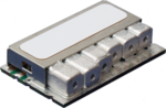
i need some tutorial to design coaxial dielectric resonator filter. What coupling technique should be used between resonators?? how to model coaxial dielectric resonators in HFSS ?? i found some pictures of such filters on internet but coupling mechanism is not apparent. Picture is attached here for reference. Kindly help me out and provide me with a design procedure of such filters.