Continue to Site

Welcome to EDAboard.com

Welcome to our site! EDAboard.com is an international Electronics Discussion Forum focused on EDA software, circuits, schematics, books, theory, papers, asic, pld, 8051, DSP, Network, RF, Analog Design, PCB, Service Manuals... and a whole lot more! To participate you need to register. Registration is free. Click here to register now.

CMOS Inverter - shortening input with output

Status
Not open for further replies.

grittinjames

Advanced Member level 1
Joined
Jun 1, 2006
Messages
479
Helped
44
Reputation
90
Reaction score
32
Trophy points
1,308
Location
bangalore india
Activity points
3,985
cmos inverter as a saturated amplifier

Hi,
I have a basic doubt, what will happen if I short input and output of cmos inverter

I am getting different answer from many experts like it will oscilates .it will move to lenear region etc .
Any one please give a satisfactory answer
no doubt you will get 10 points
 

output and input of cmos inverter shorted

1.if no signal input, the output voltage level will be the Vdd/2, just be the Vdd.Rn/(Rp+ Rn).
2.if 0 or 1 is the input ,and many inverters is cascade,they will be osillater.if only one inverter, it will be just resistor divide Vdd voltage.
3.on upper occasion, nmos in linear region, Id=uncoxw/L[2(vin-vth)vds-vds2]
 

Re: CMOS Inverter

I don't think it will oscillate, even in practical mode, because the oscillation frequency it will be so high, but the inverter has 2Cgs which brings two poles at pretty low freq compared with the oscillating freq....

Anyway, if we consider it will start to oscillate (consider Barkhausen conditions true), if the output(or input in this case) will pass throw Vdd/2 (or more precisely Vdd.Rn/(Rp+ Rn) ), the two MOS will be in saturated region, and the current will pass from Vdd to Gnd constantly. There is a possibility that the voltage established on the output to bring one MOS out from saturation (especially when Vdd is very low), but I don't think it will start to oscillate.
The two MOS will always be in saturated region because the Vds = Vgs ( >(Vgs-Vth) in nMOS case), so the two MOSes can be swapped with two current sources(controlled by voltage), but lets not forget that the MOS has Cds,Cdb,Cgs too which are pretty big . But like I said, in static state all is stable, nothing is unstable. The big question that I can think is that if the inverter is not well balanced, but I think it will reach into a stable point anyway.

Please correct me, I'm shore that I've made some mistakes...

Best regards
 

CMOS Inverter

Any one please check it practicaly for me and conform
I dont have a lab here.
Thanks a lot
 

CMOS Inverter

It depends on the CMOS inverter in question.

In principle you have a one stage ring oscillator.

But most inverters cannot oscillate at the delay time of one inverter.

Intuitively you can think of a invertor with a rise and fall time which are not equal. So the input rises, while the output falls slower, thus the output will fall, and you will reach equilibrium. I.E. the oscillator lacks memory.

If you put three in series you have a different story, because the three inverters keep triggering each other. While two inverters are switching one acts like a short term memory.

Just check it with an simulator. two transistors, power source, pulse source to bring it in a digital state. And do the transient.
 

Re: CMOS Inverter

grittinjames said:
Any one please check it practicaly for me and conform
I dont have a lab here.
Thanks a lot

Hi grittinjames,

the effect can be described as follows:
1.) The CMOS inverter transfer curve (from high to low) contains in the middle a quasi-linear region around 0.5*Vsupply - at a bias voltage which also is 0.5*Vsupply.
2.) Thus, if you bias the circuitry with 0.5*Vsupply you´ll get an inverting amplifier with a gain identical to the slope of the transfer curve.
3.) Because of 1) this bias voltage can simply generated by connecting the output with the input of the CMOS stage.
4.) Now you have an amplifier with an operating point in the middle of a linear transfer curve.
5.) However, you cannot use the circuit as an amplifier because there is a short between input and output.
6.) Therefore, if you connect input-output with a high-valued resistor you have an inverting amp which can be used.

Does this help ?
 

    grittinjames

    Points: 2
    Helpful Answer Positive Rating
CMOS Inverter

hi LVW
it helped me a lot
but my friend is still arquing that it will oscilate
plz plz some one do it practicaly for me

thanks
a lot
 

Re: CMOS Inverter

grittinjames said:
hi LVW
it helped me a lot
but my friend is still arquing that it will oscilate
plz plz some one do it practicaly for me
thanks
a lot

If your friend think it will oscillate he must be able to give the reason ! That means, he must be able to prove that the oscillation condition (Barkhausen) is met !!

Added after 5 minutes:
The CMOS inverter is able to oscillate only if the phase shift within the active frequency region (with a gain>1) is 180 deg.
I doubt if this could happen for a one-stage amplifier.
 

Re: CMOS Inverter

Hi all,

you guys had a discussion on a cmos inverter with its i/p and o/p shorted.

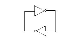
In the same lines, can you guyz comment on behaviour of inverter circuit arranged in following way :

35_1227587539.jpg


Thanks,
sp3[/img]

Added after 3 minutes:

Hi all,

you guys had a discussion on a cmos inverter with its i/p and o/p shorted.

In the same lines, can you guyz comment on behaviour of inverter circuit arranged in following way :

35_1227587539.jpg


Thanks,
sp3[/img]
 

Re: CMOS Inverter

I am trying to anser this question in two different perspectives -

1) Ideal Case
i.e two inverters are identical in all aspects . If this is the case , after powerup , two of the will try to move in same direction ( towards 1 or 0), opposing each other . Since both inverters are the same they should come in an equilibrium state .

Now in equilibrium state , assume that gain of the inverter is G . and output voltages are v1 and v2 . we have to say

v1*G = v2 and
v2 *G = v1

essentially v1 = v2 , i,e we will see the two outputs in an intermediate voltage ( neither logic high 5v or logic low 0v ) .


2) Practical Case

We are sure that no two inverters are identical . So the inverter with highest gain and input voltage gets in to Zero state and other one in high state .


i.e G1*V2 > G2*V1 -------> NOT1 will be high and NOT2 will be low

else

NOT2 will be high and NOT1 low .
 

A circuit with chain of inverters will only oscillate when the time period of the oscillation is equal to twice the propagation delay multiplied by the number of inverters chained, i..e. T = 2 Tp X N, factor of two is because a full cycle requires both - rise time and the fall time.
The above equation is valid only when
2NTp >> Tr + Tf ( rise time and fall time)
otherwise one wave of signals, propagating through the ring will overlap with the successor and eventually dampen the oscillation.

therefore typically a ring oscillator needs at least 5 inverters to be operational.

one inverter with its output and input connected together will never oscillate.
 
Status
Not open for further replies.

Part and Inventory Search

Welcome to EDABoard.com

Sponsor

Back
Top