Continue to Site

Welcome to EDAboard.com

Welcome to our site! EDAboard.com is an international Electronics Discussion Forum focused on EDA software, circuits, schematics, books, theory, papers, asic, pld, 8051, DSP, Network, RF, Analog Design, PCB, Service Manuals... and a whole lot more! To participate you need to register. Registration is free. Click here to register now.

CMFB Loop Instabilty OR Design Issue

Status
Not open for further replies.

ssuchitav

Junior Member level 3
Joined
Jun 12, 2006
Messages
30
Helped
0
Reputation
0
Reaction score
0
Trophy points
1,286
Activity points
1,487
Hi,

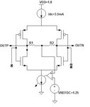
I am trying to simulate the circuit shown in the attachment. An ideal OPAMP model (dc gain=100dB UGB=1G) is used for CMFB. The input is of 100MHz.

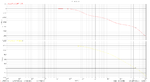
The circuit is showing unexpected rail to rail swing instead of the expected across 1.25V. I have cheked the CMFB loop stabilty and it looks fine.

Please help me in debugging this behaviour.
Thanks in advance for your suggestions.
 

Attachments

  • Quest.JPG
    Quest.JPG
    14.6 KB · Views: 101

What's the actual loop bandwith? Can you show the loop gain plot?
 

Just a remark,irrelevant with your issue..100dB for CMFB as standalone circuitry is too much,how can you realize such a large gain (which is probably larger than your amplifiers gain)?
In most cases,the biggest part of the CMFB loop-gain is located within the opamp,so the CMFB circuit as independent entity should have less gain (20-40dB let's say).

Now for your problem :
In parallel with what FvM asked you to provide can you tell us the amplitude of your input signal and also show us the output transient response for this input?
 

Hi,

Please see the AC response and the setup for the same.

I have also attached the transient behaviour of the circuit.

I forgot to mention about the termination in my original post. This can be seen in the setup.

Best Regards
 

Attachments

  • transient_RESPONSE.png
    transient_RESPONSE.png
    49.6 KB · Views: 105
  • AC_RESPONSE.png
    AC_RESPONSE.png
    27.4 KB · Views: 103
  • Setup.png
    Setup.png
    95.8 KB · Views: 107
Last edited:

You apparently misinterpreted the loop gain diagram. There are 3 poles below respectively near the unity gain frequency and a negative phase margin. You build an effective oscillator. For present pole locations, you have to reduce the gain by 70 to 80 dB.
 

This is not rail to rail swing,this is oscillations!Thus,you must investigate for the cause of instability.
 

I'll try this out.

Btw, does a negative phase, not equal to -180, @gain=0dB i.e. UGB cause instability?
 

Ofcourse.Remember the definition of Phase Margin and how it comes out from Nyquist's diagram.You measure the distanse of the phase at Gain=0dB from -180deg.PM must be always positive to ensure stability.Typically must be in effect PM>45deg.
 
You should try achieve 40 to 50 degree phase margin. Near zero or negative phase margin will cause oscillations in most cases.
 

Thanks.
I'll rework on this.
 

Status
Not open for further replies.

Similar threads

Part and Inventory Search

Welcome to EDABoard.com

Sponsor

Back
Top