Vermes
Advanced Member level 4

This clock with additional functions of date and thermometer is built on six Nixie tubes.
Assumptions:
- use of AVR microcontroller
- one-sided PCB
- possibility to maintain timing (RTC apply)
- display multiplexing (one 74141 apply – reducing the costs)
- date display
- separate PCB for tubes and driver (driver PCB can be used with various models of tubes)
Hardware:
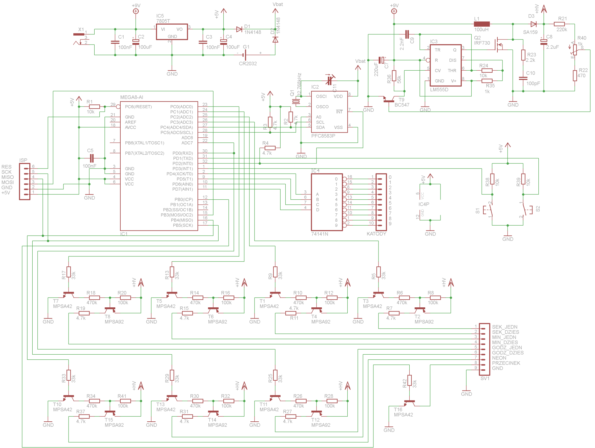
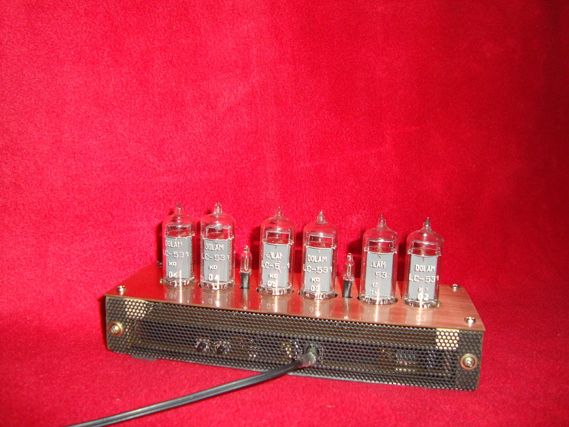
The construction was based on another similar project from **broken link removed**. The device consists of LC531 Nixie tubes, Atmega8A and RTC PCF8583. Battery CR2032 maintains the RTC operation. Converter that powers the tubes is based on NE555 in SMD version and transistor IRF730. There is a row of six HADERS, because there was not enough space for standard socket of programmer IDC10. Lamps and neons are lit by pairs of transistors MPSA92 and MPSA42. The whole is powered from a plug power supply that provides 9V (current consumption is about 150-250mA).
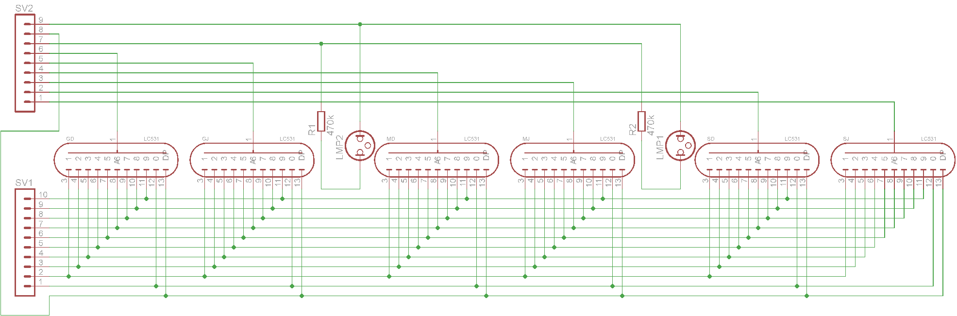
Schematic of the driver PCB and tubes:
Software:
Program was written in C in AVR Studio 4. You can be supported by note sheet of Atmega, PCF and information found on the Internet. Library for the TWI (I2C) interface handling (Atmega<-> PCFcommunication) can be downloaded from HERE. Atmega works with internal oscillator set to 2MHz. TIMER2 generates the multiplexing frequency.
Assembly and start:
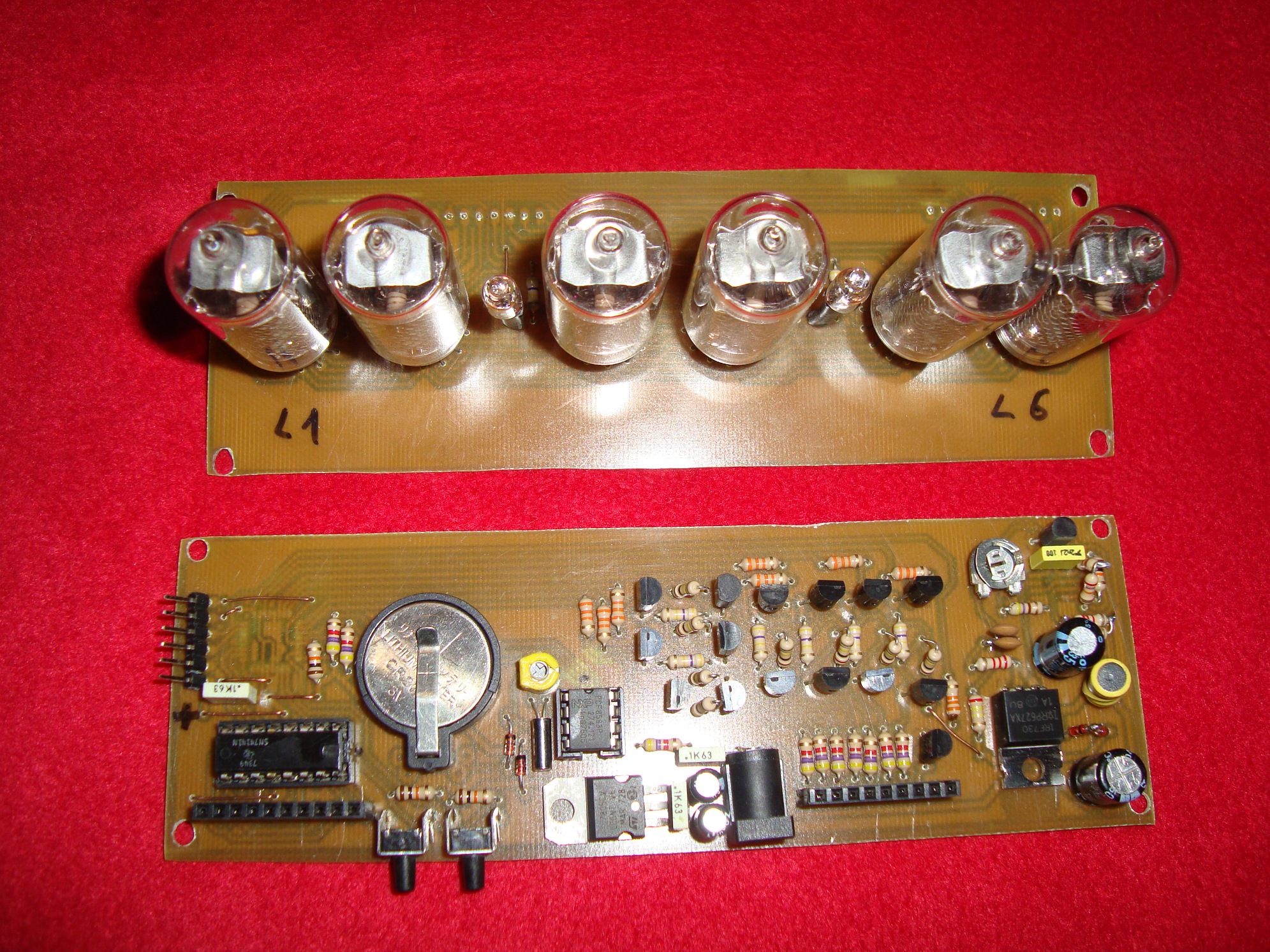
PCBs were made in thermal transfer method using a laminator. It is good to start work with soldering the components of the converter and test it. Choke applied in the converter should have specific parameters (100uH, 0,5A). Next, it is recommended to mount the elements responsible for filtering and stabilization of voltage powering Atmega and RTC. Once checked whether the voltage at the third pin of the 7805 is 5V, you can start mounting the rest of components.
Brightness of the tubes (output voltage of the converter) can be controlled by potentiometer R40. Do not set the maximum voltage, because that could cause rapid wear on the tubes. Trimmer C11 controls the work of PCF8583 (changing the trimmer settings you can cause the timing speeds up or slows down). Neon current limiting resistors values should be chosen so that their brightness is similar to the brightness of the tubes (for example, 470k resistors).
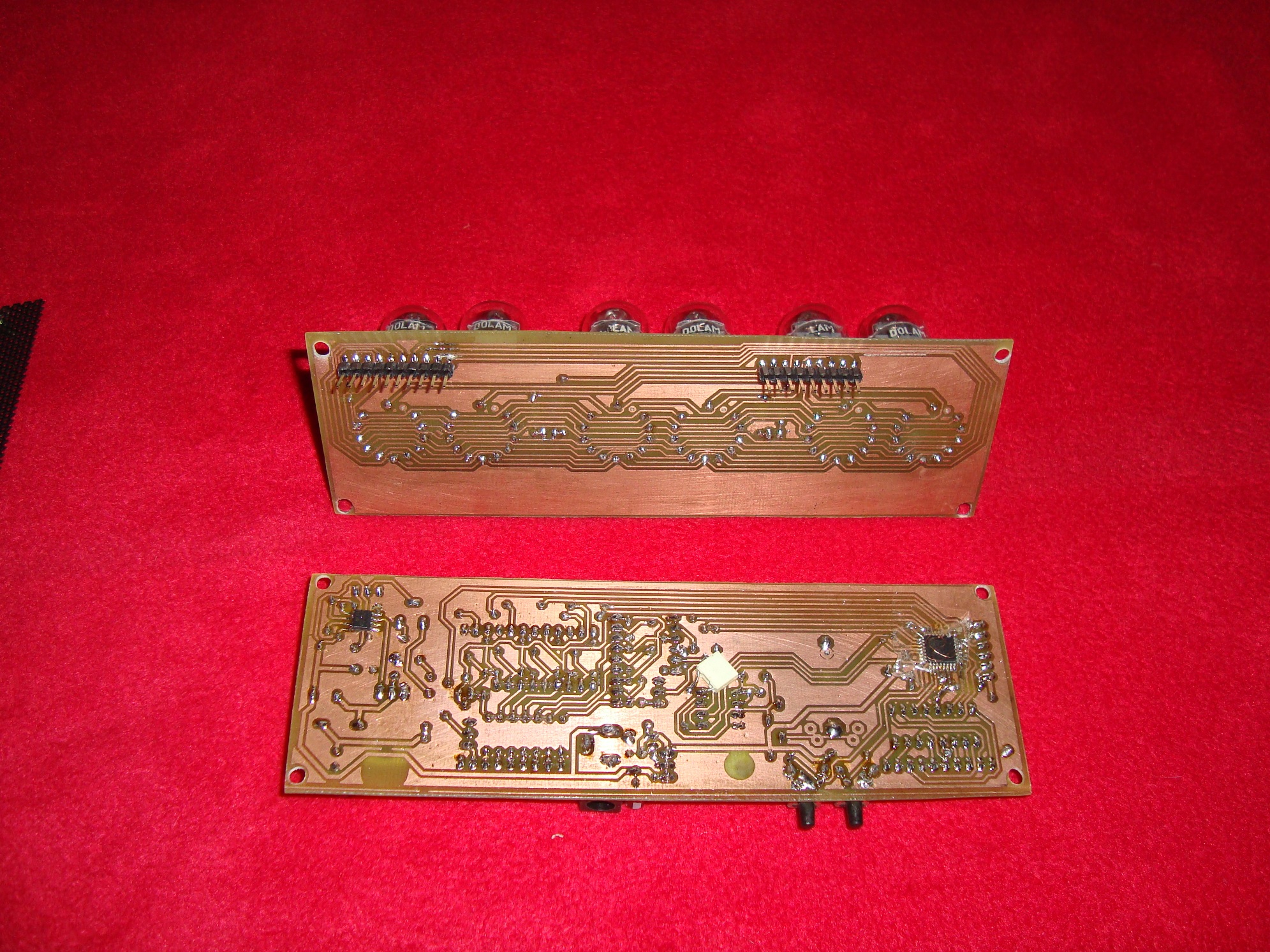
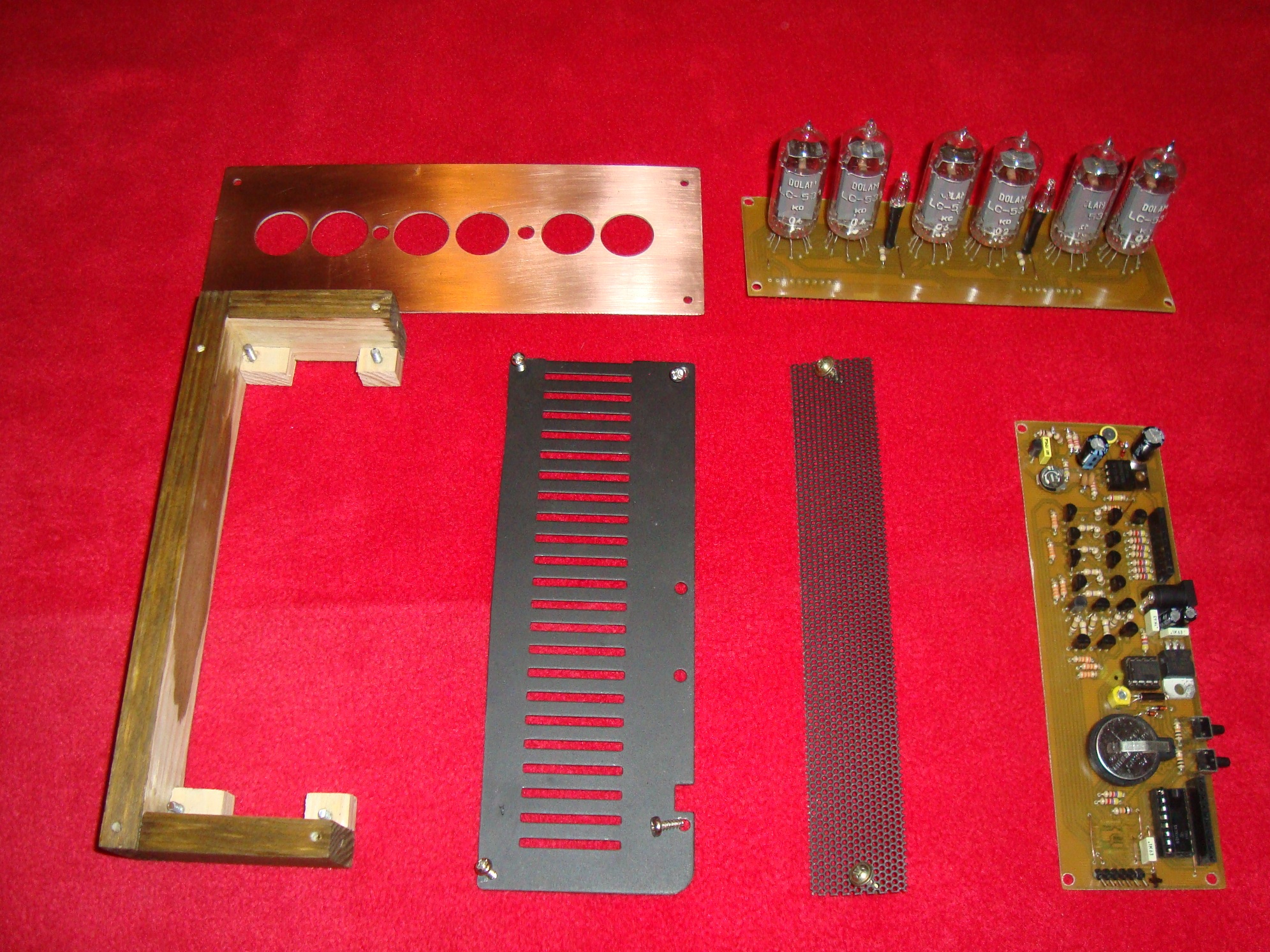
Pictures of the PCBs:
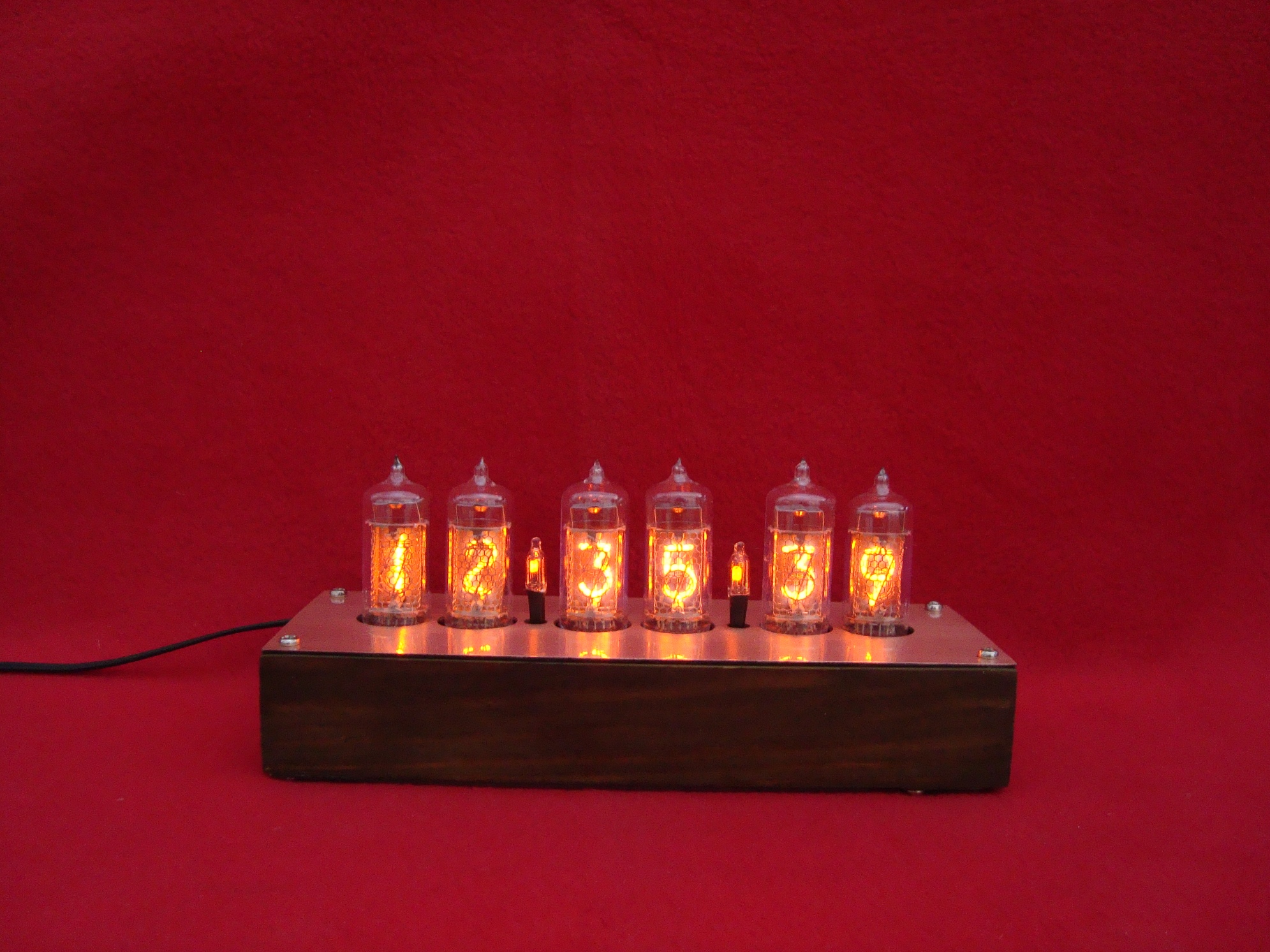
Using two buttons, you can set the time and date. After pressing the 1 button, the clock operation stops. Using the 2 button you can change the value of hour (tens). After again pressing 1 button, you switch to edition of hour (units), etc. After setting the time, you can set the date using the same method. Each digit which is currently edited, is distinguished by lit coma in the tube. The whole procedure of setting the clock is shown on the following video:
Housing:
Rear part of the housing is a grid that protects the speaker in TV. The bottom is a cut lid of an amplifier. Both these components were painted black using a spray. Sides and front are stained and varnished slats glued together with Wikol adhesive. The top cover consists of a brushed PCB, covered with a layer of varnish.
Elements of the housing:
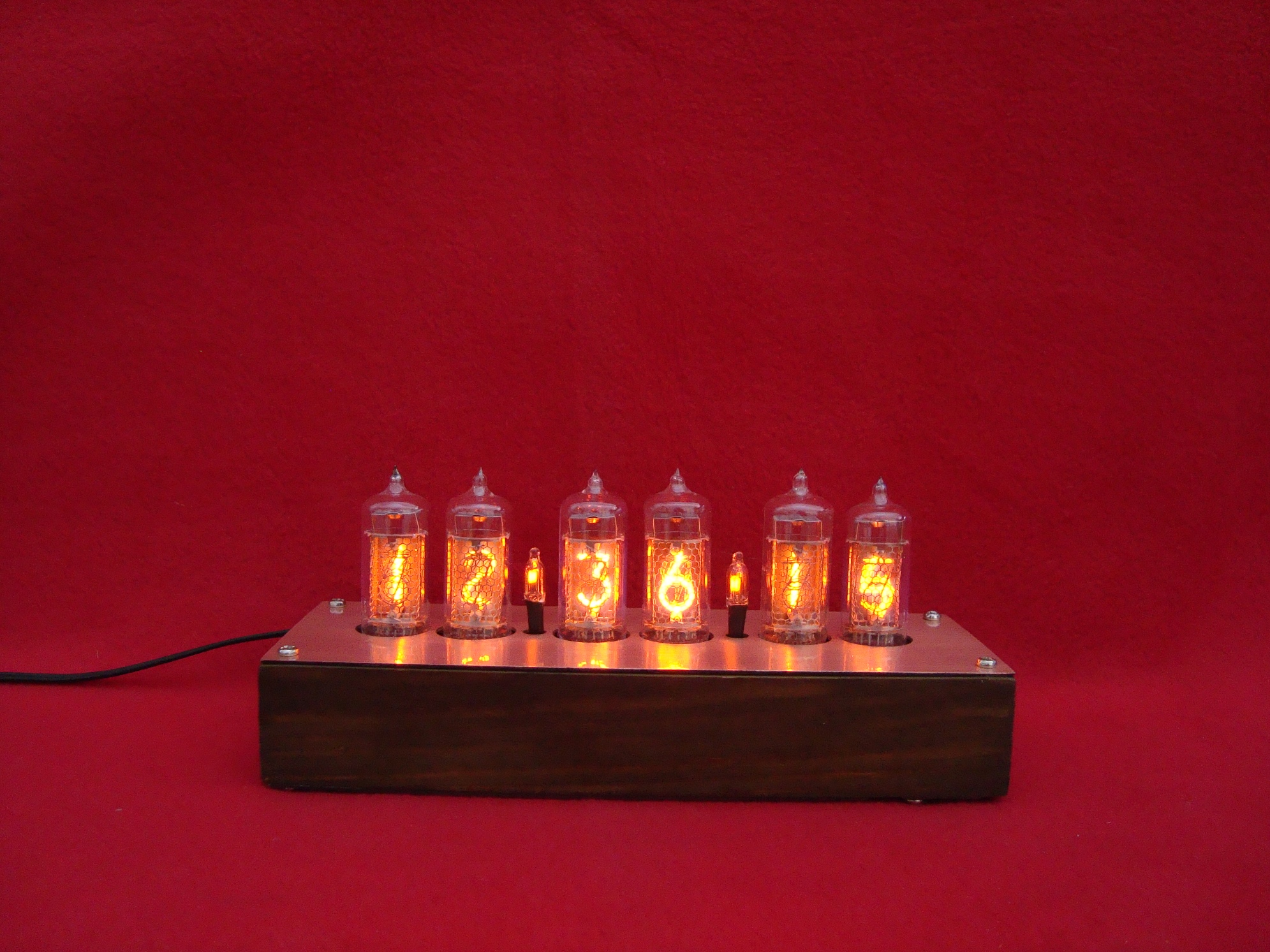
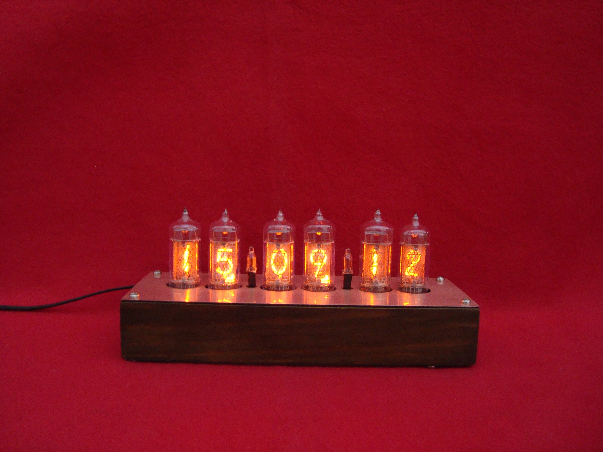
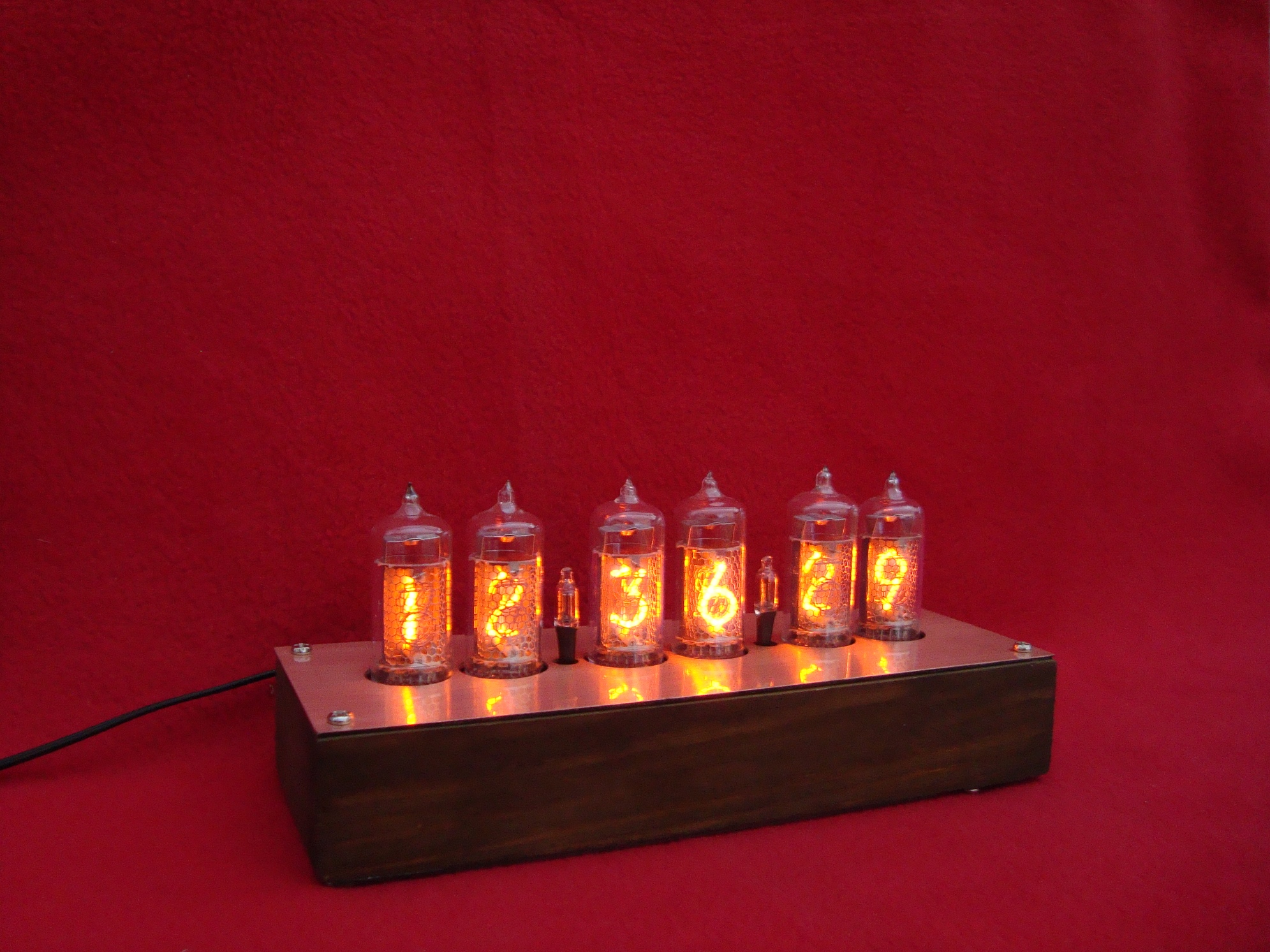
Pictures of the clock:
And a video:
The design was also developed by temperature measure using sensor DS18B20. Software support of the sensor can be found on the Internet – search for rklibavr library.
During displaying the temperature, only 3, 4 and 5 tubes are lit (temperature is displayed in the form of eg 26,3). Negative temperature is indicated by lighting the coma in the 2 tube.
To add temperature measure, you have to modify the driver:
- add a sensor DS18B20
- change angle buttons to standard ones
- change the position of elements C7, C8 and L1 – they can be mounted horizontally and thus the distance between the PCBs can be reduced
- a parallel connected capacitor can be added to the trimmer in order to improve the accuracy of time regulation
It is good to mount the buttons and trimmer from the side of print, just drill three holes in the bottom side of the housing. This solution will allow you to have an easy access to the elements responsible for the clock regulation without the need to unscrew the housing.
Link to original thread (useful attachment) - Zegar, data, termometr Nixie LC531/IN14 na Atmega8A i PCF8583