viperpaki007
Full Member level 5

- Joined
- Jul 2, 2008
- Messages
- 274
- Helped
- 11
- Reputation
- 22
- Reaction score
- 8
- Trophy points
- 1,298
- Location
- Finland
- Activity points
- 3,437
Hi,
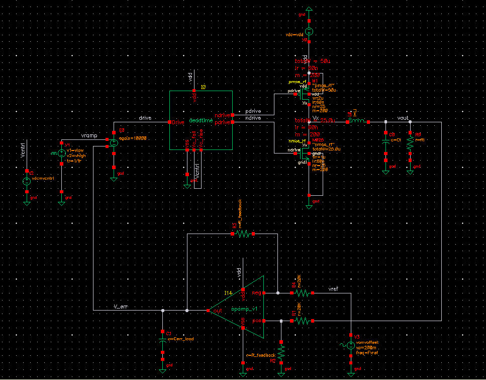
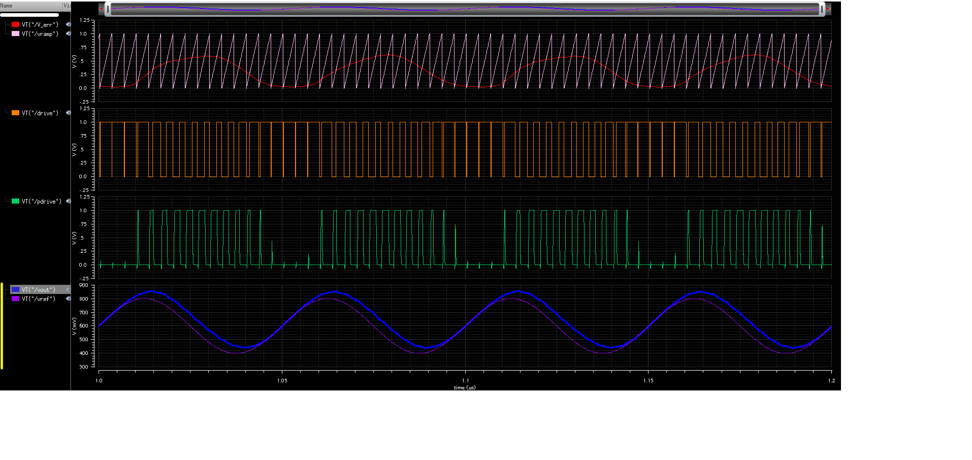
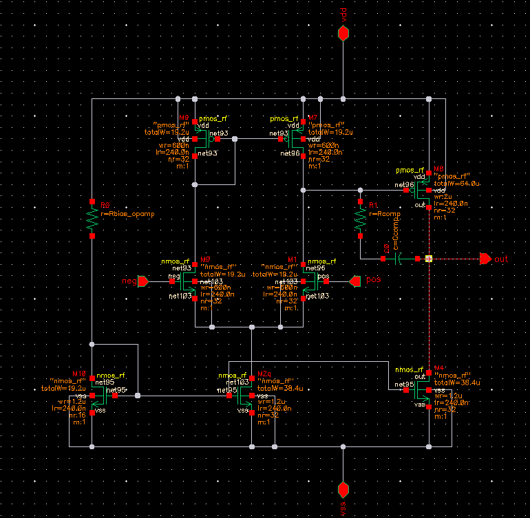
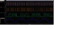
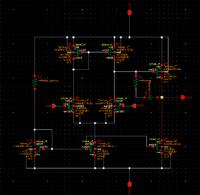
I designed a class D switching converter with PWM feedback. Circuit diagram is attached. Now i am having problem in understanding the stability of overall PWM feedback. What should be the properties of error amplifier in this configuration. Moreover, though i have implemented PWM feedback using an opamp in summing configuration, i have no idea how the system really works in terms of stability/loop gain etc. The results shown have been achieved based on trial and error approach and there is a dc offset in reference voltage (vref) and output voltage (vout). I have no idea why this dc offset is present. Can somebody give me a theoretical link to study or explain the concept so that i can design the converter with better understanding.
I designed a class D switching converter with PWM feedback. Circuit diagram is attached. Now i am having problem in understanding the stability of overall PWM feedback. What should be the properties of error amplifier in this configuration. Moreover, though i have implemented PWM feedback using an opamp in summing configuration, i have no idea how the system really works in terms of stability/loop gain etc. The results shown have been achieved based on trial and error approach and there is a dc offset in reference voltage (vref) and output voltage (vout). I have no idea why this dc offset is present. Can somebody give me a theoretical link to study or explain the concept so that i can design the converter with better understanding.