vinay13
Newbie level 5

- Joined
- Apr 2, 2013
- Messages
- 10
- Helped
- 1
- Reputation
- 2
- Reaction score
- 1
- Trophy points
- 1,283
- Activity points
- 1,354
can some one help me with the biasing of BD139 and BD140 to operate in classAB amplifier
Follow along with the video below to see how to install our site as a web app on your home screen.
Note: This feature may not be available in some browsers.


what u said is correct but i have used diodes for biasing the base of BD139 and BD140 to 0.7v and i want to get maximum current from the class AB around 1Amp and my input is 30Vp-p sine wave.but one more thing i noticed is tht as i reduce the input wave peak to peak voltage the current drawn increases and vice versa. one more thing is tht even whn there is no input signal the transistors still draw current which indicates tht the transistors arent biased into class AB configuration i suppose . plz i need help urgently.


How about showing your circuit?but i have used diodes for biasing the base of BD139 and BD140 to 0.7v and i want to get maximum current from the class AB around 1Amp


There's a high risk to exceed BD139/140 power rating in your circuit. I guess you'll want to use "stronger" transistors.my circuit draws around 550mA of current and the load is a coil.
i want to draw maximum current and supply to the load .

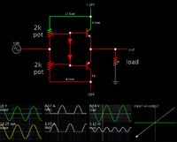
here u go thts my circuit View attachment 88997
my circuit draws around 550mA of current and the load is a coil.
i want to draw maximum current and supply to the load .

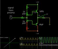
The idea is to drive the transistors to their minimum 'On' resistance. That is how you will obtain maximum swing. To do this, you need to apply large signal current, as well as sufficiently large bias current. Hence it works best if your biasing arrangement contains the least amount of components.
Your circuit can work. It is typical of class AB designs which may be found on the internet. The diodes create an automatic voltage separation between the upper and lower bias wires. However if the diode has a higher threshold V than the bias, it starts to waste excessive quiescent current. The transistors are asked to dissipate excessive watts as heat.
So, after trying many simulations over time, I find the post #2 schematic allows you to fine-adjust values so as to waste the least current. This is important, because you are powering your amplifier from a high supply V. The voltage drops become substantial enough to create several watts of heat in your transistors.

can someone help me with short circuit or over current protection circuitry for class AB amplifier...!!
I replaced BD139 and BD140 with BDW42G and BDW46G and now my class AB amplifier is working fine...!!! thanx for the help if u have anymore information on class AB u r welcomed to share it and also some designs on over current and short circuit protection circuitry for class AB amplifier...!!


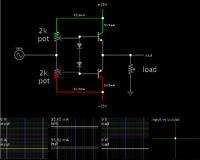
The only thing you need to change is the value of the 1Ω emitter resistors at the output. The 2N3904 and 2N3906 transistors will switch on and limit the output current when their base-emitter voltage reaches about 0.7V.can u help me with the calculations needed to be done in order to choose values for the protection circuitry.

The only thing you need to change is the value of the 1Ω emitter resistors at the output. The 2N3904 and 2N3906 transistors will switch on and limit the output current when their base-emitter voltage reaches about 0.7V.
So maximum output current = about 0.7V / Re. With Re = 1Ω, the output current should be limited to about +-0.7A

It may not really be needed, but it is a good idea, just to be safe. 1K is fine.do i need to connect a current limiting resistor at the base of 2N3904 and 06????
I would connect a low resistance load to the output, then slowly increase the signal amplitude, while watching the output with an oscilloscope, to see what voltage the output is limited to.and how do i test the protection circuit to see if its actually working the way it is supposed to ??


It depends...fine i'll try doing tht and what if i directly short ma output with the ground??? will my circuit still be protected from overcurrent???