Continue to Site

Welcome to EDAboard.com

Welcome to our site! EDAboard.com is an international Electronics Discussion Forum focused on EDA software, circuits, schematics, books, theory, papers, asic, pld, 8051, DSP, Network, RF, Analog Design, PCB, Service Manuals... and a whole lot more! To participate you need to register. Registration is free. Click here to register now.

[SOLVED] Clamp Diode on High Speed Lines

Status
Not open for further replies.

cks3976

Full Member level 6
Joined
Aug 8, 2007
Messages
344
Helped
84
Reputation
168
Reaction score
81
Trophy points
1,308
Location
India
Activity points
3,324
Hi,

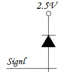
Can I use Diode termination (Diode clamping) on a high speed CMOS line ? Speed of this line will be 250MHz. What will be the impact on the signal speed & switching ?

Secondly are there any other impacts such as power dissipation by the Diode on the clamp source voltage and radiation ?

I have attached the clamping diagram for your convenience.

Looking forward for suggestions from you all..

Thanks in Advance,
CKS

91_1324543771.png
 

One question is if the length of your line is long enough to generate transients to be clamped. Another question is what are the parameters of your clamping diode.

Diode connected according to the schematic opens when the line voltage exceeds 2.5 V Vcc plus ~ 0.7 V of diode P/N junction. Diodes have also a P/N junction capacitance when not open; at 250 MHz, this capacitance ( 0.5...2 pF) on a long line may affect signal spectrum and pulse shape.
Any inhomogeneity on a "clean" line will cause reflections, radiation, etc. A correct device to prevent this is a matched resistor, with a resistance equal to line impedance.
For signal like 250 MHz, I would suggest to check "www.hittite.com", for line-terminating circuits; those seem to be better than clamping diodes.
 
  • Like
Reactions: cks3976

    cks3976

    Points: 2
    Helpful Answer Positive Rating
Status
Not open for further replies.

Part and Inventory Search

Welcome to EDABoard.com

Sponsor

Back
Top