Continue to Site
Follow along with the video below to see how to install our site as a web app on your home screen.
Note: This feature may not be available in some browsers.
Agreed in principle, but did you read the Wikipedia article linked above ?inductors and capacitors cannot be replaced by a voltage regulators since they have totaly different characteristics.
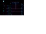
It would help to know what type of IC it is on the right, what IC package is used (DIP, flat pack, BGA, ...), and on what sort of board it's located (single/double/four-layer board etc).