Continue to Site

Welcome to EDAboard.com

Welcome to our site! EDAboard.com is an international Electronics Discussion Forum focused on EDA software, circuits, schematics, books, theory, papers, asic, pld, 8051, DSP, Network, RF, Analog Design, PCB, Service Manuals... and a whole lot more! To participate you need to register. Registration is free. Click here to register now.

[SOLVED] Circuit to Split Single DC Supply into 3 Voltage Levels

Status
Not open for further replies.

hshah8970

Full Member level 2
Joined
Sep 17, 2011
Messages
144
Helped
18
Reputation
36
Reaction score
18
Trophy points
1,308
Activity points
2,385
Hello everyone. I'm designing a circuit using opamps to drive a DC motor. So far I've been using 3 DC supplies to power up the circuit: 2 supplies for the +Vcc and -Vcc of the opamps and one supply for the voltage input to the opamp.

I know there must be a way for me to provide all these different voltage levels through a single DC power supply. I found this informative article online that does the job but I wonder if the circuit suits my specifications: **broken link removed**

My requirements for the three voltage levels are:

1. +Vcc and -Vcc should have opposite signs and a difference of at least 8V between them, with +Vcc being equal to at least 9V.
2. The third voltage level should be a variable one because this is the one I will be using for control.
3. The DC supply being used will be set at its maximum value which is +16V. The minimum value is zero / ground.
4. The maximum current being delivered to the circuit will be 6A.

Assistance will be highly appreciated.

Humza.
 

2. The third voltage level should be a variable one because this is the one I will be using for control.
You don't need a separate power supply for this. You can get the control voltage from the main power supply, using a potentiometer to set the voltage you want.

1. +Vcc and -Vcc should have opposite signs and a difference of at least 8V between them, with +Vcc being equal to at least 9V.
I'm still not quite clear what you want to achieve. If you only need the motor to turn in one direction then you probably don't need a negative supply. i.e. You only need one power supply.

If you want the motor to turn in both directions, there are two ways to do it:
  • Use one power opamp and two power supplies, as you suggested, one positive and one negative.
  • Use two power opamps and a single power supply.

I'm designing a circuit using opamps.....
It sounds like you're already using more than one opamp. If you show your circuit, we can get a better idea of what you're doing.
 
I shall make a proper circuit schematic later today or early tomorrow and post it here to better explain. Thanks for your response.

And yes: multiple opamps (two OPA549) and the motor turns in only one direction.
 

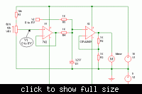
Here is a simple circuit schematic of what I'm trying to do. The 3 different voltage levels I will be requiring from the DC supply include V1, Vcc, and -Vcc.

A short description of the circuit: the DC motor will be running through the initial voltage level V1; this level should be variable so that we can control the motor speed. V2 is an external DC voltage that will be introduced in the steady state to check effects of its introduction. V1 and V2 will be summed by opamp U1 and then fed to the motor through opamp U2.

A few circuit specifications:

1. The main DC supply (from which I will be getting voltage levels) goes as far as 16V.
2. The motor draws as much as 5A of current.
3. V1 should go up till 8V. V2 will go up till 5V.
4. Opamps I have with me include two OPA549, one OPA497, and one UA741. I was thinking of using OPA497 or UA741 as opamp U1 for voltage summing since I think they consume lesser power than OPA549. U2 needs to be OPA549 since the motor's current requirement is high.
5. The motor will be turning in only one direction.

P.S. I shall try using ground as -Vcc but if that doesn't work (as it hasn't in an earlier test) then I'll need a negative voltage input for -Vcc. Also, will I be needing different Vcc levels for different opamps?

A zener diode will be used to protect the motor from accidental overvoltage since it is rated at 12V.

Sch.png
 

You have U2 serving as a resistive drop, in order to vary the current going through the motor.

This method causes U2 to get extremely hot as it dissipates wasted power.

You'll generate less heat in U2 if you use pulses to vary motor speed. This means switching it all-on, all-off, rapidly. It's more efficient.

You need not alter the supply.

Since you are turning the motor in one direction only, the switching device can be a single transistor or mosfet.

The control circuitry could turn out to be more complicated than your present schematic.
 
@bradtherad:
Thanks for your response. Yes, I'm aware of the heat being dissipated within U2 but I shall not be incorporating PWM into the design at this stage.

If the power wasted was more than I could ignore, then I'll focus on a PWM implementation.
 

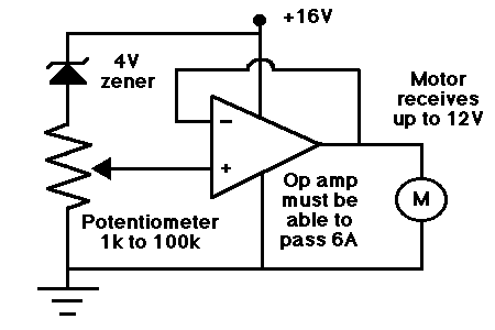
In its simplest form this is how the op amp can do all jobs of providing power to the motor and also be the control device:

The output will be able to go down to 0V, since the OPA549 can operate on a single supply.

72_1340385113.gif


A more elaborate driver circuit is at this link. It adds diodes as safeguards, to absorb motor kickback when it is shut off.

http://www.datasheetdir.com/OPA549+High-Voltage
 
@bradtherad:
Thanks for the schematic! And yes, I'm aware of the snubber circuit + diodes configuration in OPA549's datasheet.

I added in the second opamp just to eliminate the motor's loading effect but now that I think about it, I feel I can get rid of the voltage follower without much harm done.

However, the voltage summer needs to be there. The V2 voltage will be introduced later and it needs to be summed with the original voltage. I shall take the V1 from a potentiometer configuration.

One basic question to confirm: in your schematic, the voltage drop across the potentiometer can be a maximum of 12V, right? (because of the 4V zener)
 

P.S. I shall try using ground as -Vcc but if that doesn't work (as it hasn't in an earlier test) then I'll need a negative voltage input for -Vcc. Also, will I be needing different Vcc levels for different opamps?
Both uA741 and OPA549 can be used with a single +16V supply or a dual +-16V supply. There is a slight problem with the 741 in this application though - it's inputs and outputs can't go all the way down to the negative supply voltage. That's why you had problems earlier using a single supply.

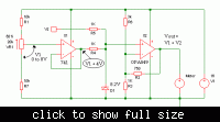
You could use a circuit like the one below. The negative supply isn't critical. It can be anywhere between about 5 to 15V, and doesn't have to supply much current.


- - - Updated - - -

If you want to do everything with one supply, you need to lift V1 above ground e.g. with a circuit like this. The Zener is 8.2V because 8V at that point gives 12V across the motor.

 
I've cobbled up a simple charge pump before using a LM555
timer and the usual diode-capacitor networks, one rigged
for positive and one for negative. It gets me the +/-12V I
need from a car battery. I'm just running an instrumentation
amplifier with it, so current-throw is not an issue.

There's a lot of cheapo DC-DC converters on eBay. Make
vs buy cost says get one unless you're looking to amuse
yourself with this problem.
 
Status
Not open for further replies.

Similar threads

Part and Inventory Search

Welcome to EDABoard.com

Sponsor

Back
Top