yassin.kraouch
Advanced Member level 2
Hello, Please i am blocked on this situation : i have an input voltage between 3 and 20 V, i want that the voltage do not exceed 14 V, have you an idea on how to do this ?
Follow along with the video below to see how to install our site as a web app on your home screen.
Note: This feature may not be available in some browsers.
is there any thermal risk, if the voltage is 20 V or 24 V ?
Voltage regulators such as 78XX, 317 and similar, can not work properly with input voltages lower than V[out]. In fact, most of them will require that the input voltage is about 3V higher than the output voltage.Hello, Please i am blocked on this situation : i have an input voltage between 3 and 20 V, i want that the voltage do not exceed 14 V, have you an idea on how to do this ?
The problem is that i need 500mA and i am worried about heat problem, really i am blocked, my idea is to use two output transistor in parallel but i am worried of the current imbalance between two transistor :/Voltage regulators such as 78XX, 317 and similar, can not work properly with input voltages lower than V[out]. In fact, most of them will require that the input voltage is about 3V higher than the output voltage.
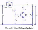
What you can consider for applications where the input voltage can go as low as 3V is a shunt (or parallel) regulator build of a Zener diode, Power Transistor mounted on a Heatsink and a small properly rated series resistor, as shown on the attached picture.
More info here:
https://www.circuitstoday.com/zener-controlled-transistor-voltage-regulators
:wink:
IanP
Dear picgak, yes this is the solution i am trying to validate now, but there is many issues, available space, i have just 40mmx10 mm, also if i used MJD31CT4, but there is some thermal risk if the ambient temperature is 85°, i thought on putting two pass transistor in parallel but, i am worried about the imbalance current between the two pass transistorHi yassin.kraouch,
Your problem is very simple, Use a series pass NPN transistor (say 2n3055) connect a zener diode available say 14.6v or below 14.6v between the base and -ve, put a resistor from collector to base near 470 ohm, you will get the required voltage from the emitter. Hope your problem is solved, dont forget to click the helpedme button below.
regards ani
- - - Updated - - -
Hi yassin.kraouch,
I forgot to tell you please connect the varying +ve voltage to the collector of 2n3055
what do you think about parallel transistor solution ? will this cause a current imbalance ?First guess, dissipating 3W in 40mm*10mm PCB at 85 degrees ambient will result in too high junction temperature for Silicon. If the load has large capacitance on board, even the inrush peak may damage/destroy the transitor(s), especially after cycling power under worst case situation.
Using more smaller transistors (in DPAK ?) spread over the PCB area may result in acceptable junction temperature. It may also save you from second breakdown issues (check the DC SOA). If you can accept around 0.7V drop, you can use PNP transistors with current sharing resistors. 300mV across each resistor is sufficient. You can buy so called "low VCEsat" transistors that I used for similar applications (Diodes/zetex, NXP (former Philips), etc). Your MJD31/ MJD32 looks good, only the hfe is low. Maybe you need two of them.
If the dissipation is a problem, you have to go to a switching solution.