Continue to Site

Welcome to EDAboard.com

Welcome to our site! EDAboard.com is an international Electronics Discussion Forum focused on EDA software, circuits, schematics, books, theory, papers, asic, pld, 8051, DSP, Network, RF, Analog Design, PCB, Service Manuals... and a whole lot more! To participate you need to register. Registration is free. Click here to register now.

Circuit problem. Not getting 5 Volt on 7805 output

Status
Not open for further replies.
So basically it rather acts as an open source output.
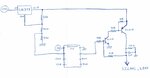
More like open drain in that configuration but driving the output latch high makes the TRIS (tri-state) bit behave like an open source pull-up.
More generally with PICs, if the output s driven low and the TRIS register (has one bit per port bit) is used instead of the PORT register it can be used in open-drain fashion to interface to devices that can only tolerate low voltages. A PIC on 5V can drive a 3.3V device for example if the pins are externally pulled up to the 3.3V supply.

Brian.
 

Hello everyone again,
Today I have tested these solutions presented here and both work fine.
I will use the solution using the TRIS bit of my PIC pin to switch from 5V to 8V and produce the signal that I want.
However it is important for me to have a solution to prevent a circuit failure if the signal wire has a short circuit to ground.
I have already tried many Fuses but I am not being able to use them correctly. It seems that LM317 is protecting against the short circuit and the fuse doesn´t blow. However LM317 gets very hot and I think that if it stays in this short circuit state for a long time it will fail.
So, I have been thinking about another solution.
Please check the following image.
Note that I only have 1 free pin on my PIC to use. If I had two Pins available I would use one pin as ADC to check if there is a short circuit on the
Signal Line and with the other pin I would enable or disable a Voltage regulator with this function.
But I only have 1 free Pin to use and don´t want to use a bigger Pic.

So, my solution is: When the system is turned ON the pic will have 5V output for 2 seconds. This will turn ON both transistors and the current will flow from
the LM317 to the Signal Line output. After 2 seconds the PIC turns OFF this output. But as you can see on my image if the Signal Line is high it will also turn ON both transistors.
So, the transistors will always be ON until a short circuit to ground happens.
If a short to ground happens, both transistors will be OFF and no current will flow from LM317 to the Signal Line.
Then, only when the system is turned OFF and ON it will work again.

I have tested this solution and it works.
However I am sharing with you to know your opinion and to know if you are seeing a simpler solution ?

A simpler solution was to use a voltage regulator with enable Pin but all that I found the enable Pin is ON when you have ground. And was looking for the opposite but could not find.

Again, many thanks for your help.
 

Attachments

  • Scheme.jpg
    Scheme.jpg
    170.9 KB · Views: 153

Hi,

My idea is to use a current limiting circuit.
You may use it before the voltage regulator, then the output voltage is precise as long as the current is within it's valid range.

Klaus
 

You might want to consider putting the PNP transistor switch at the input to the LM317 instead of the output.
That way the ON saturation voltage of the transistor won't affect the output voltage of the LM317 to the load.
Also such a connection will eliminate the bias current of the LM317 when off.
 

My understanding is, that the LM317 incorporates thermal limiting that allows it to sustain an output short forever?
 

My understanding is, that the LM317 incorporates thermal limiting that allows it to sustain an output short forever?
Perhaps a little less than that.:smile:
The thermal limiting occurs at a junction temperature of 180°C (from LM317 data sheet below), which is well above the maximum operating temperature of 150°C, and that could shorten its lifetime.
But that's probably not an issue in most applications.

Capture.PNG
 
Last edited:

A quick way to detect a short circuit to ground if you have a free pin on the PIC is to use it to monitor the output voltage.

Wire a potential divider across the output of the regulator such that 8V gives 5V at the center. Then read that in to the PIC as a digital signal. 8V will give 5V and 5V will give 3.125V, both well above the 'high' threshold. If the input reads as zero you have a short to ground or significant overload.

Brian.
 

Yes, that is an easy solution. But that solution requires 2 pin´s from the PIC and I only have 1 free.
I think it requires 2 pin´s. The first as an analog input to read the voltage at the pin with the ADC function.
Second pin as an output to control the gate of the transistor or mosfet. Right ?
 

Would you want to add an "electronic fuse" circuit which will shut off the current to the LM317 if it exceeds a certain value?

Example circuit and simulation below:
The fuse is reset by removing the power or the short.

Capture.PNG
 
think it requires 2 pin´s. The first as an analog input to read the voltage at the pin with the ADC function.
Second pin as an output to control the gate of the transistor or mosfet. Right ?

You don't need the ADC, if all you want to detect is whether the output is there or shorted out, a digital input will do.
I think you need to clarify your requirements, do you want to limit the output current so the output stays on but the voltage drops if it is overloaded or do you want to cut the power if overloaded and if so how do you want to restore it.

Brian.
 

Status
Not open for further replies.

Part and Inventory Search

Welcome to EDABoard.com

Sponsor

Back
Top