megs
Newbie level 3

- Joined
- Feb 10, 2005
- Messages
- 3
- Helped
- 0
- Reputation
- 0
- Reaction score
- 0
- Trophy points
- 1,281
- Activity points
- 20
Follow along with the video below to see how to install our site as a web app on your home screen.
Note: This feature may not be available in some browsers.


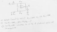
Since there is both positive and negative feedback, it's a lot to expect for anyone to predict the shape of the resulting waveform, and its amplitude. The different feedback loops interact to some extent, depending on the ratios of the resistors.
If there were only negative feedback it would be relatively easy to calculate the result.
Or if there were only positive feedback, it would create hysteresis action. The range of the hysteresis loop would take some effort to calculate.
If those are limiting diodes at the output, then I think they are zener diodes.
By experimenting with a variety of feedback resistances, it is possible to obtain a sinewave, or square wave, or clamped sinewave.


If R1 > 10K, then negative feedback is greater than positive feedback, so the circuit is a linear amplifier and you can calculate the gain as Vo/Vi.
If R1 < 10K, then positive feedback is greater than negative feedback, so the circuit is a Schmitt trigger, and you can calculate the input voltages required at the input to switch the output high and low.


Hi BradtheRad,
Thanks for your response. Could you please shed some light on how I can find out what decides the shape of the wave and how I go about it? I found the Av-voltage gain (1.2) ie vo/vin by doing the circuit analysis.
Any good reference?
Thanks,
Meghana