Continue to Site

Welcome to EDAboard.com

Welcome to our site! EDAboard.com is an international Electronics Discussion Forum focused on EDA software, circuits, schematics, books, theory, papers, asic, pld, 8051, DSP, Network, RF, Analog Design, PCB, Service Manuals... and a whole lot more! To participate you need to register. Registration is free. Click here to register now.

circuit analysis

Status
Not open for further replies.

parth22

Member level 4
Joined
Mar 15, 2022
Messages
78
Helped
2
Reputation
4
Reaction score
1
Trophy points
8
Activity points
518
Hi all,
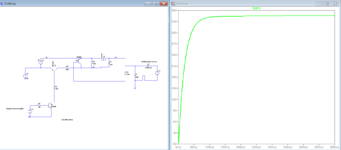
I have this PMOS circuit and would like to figure out this working.
I would like to know why the M1 is working while the Q5 is always on. As Q5 is always on, it will pull the source to Gate which should turn off the PMOS.

Am I getting this in the wrong way or something else?
Thanks.
 

Attachments

  • 1654509687184.png
    1654509687184.png
    39 KB · Views: 79

Why do you think that M1 is "working"? R6 charges the output without M1 turning on.

You can find out yourself by looking at circuit node voltages and branch currents, that's the purpose of a simulation.
 

Why do you think that M1 is "working"? R6 charges the output without M1 turning on.

You can find out yourself by looking at circuit node voltages and branch currents, that's the purpose of a simulation.
yes I check. There is no current through M1. M1 is not conducting.

And I got it. R6 is charging C1 from Q5 base. It means to charge the C1 we don't need PMOS anymore.
Thanks.😊
 

Status
Not open for further replies.

Similar threads

Part and Inventory Search

Welcome to EDABoard.com

Sponsor

Back
Top