Adam-x
Newbie level 2

- Joined
- Dec 22, 2012
- Messages
- 2
- Helped
- 0
- Reputation
- 0
- Reaction score
- 0
- Trophy points
- 1,281
- Activity points
- 1,299
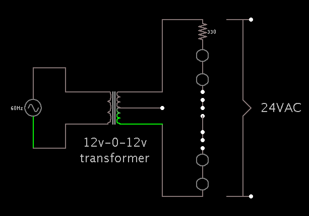
Quick scenario. I bought LED Christmas lights, transformer sold separately. shop doesn't stock it... 

The light set rating is 24V at 0.7W. The Light component is made up of 3 lines 1 negative and 2 positive and end in a male and female jack so you can ad extra light sets. Individual lines offer resistance but none of the alternating connections do, so all 3 lines are independent. I assume the "sold separately" transformer either has an input and output connection or comes with a 'terminal' set of lights that closes the circuit.
I bought a 240V (standard mains voltage) to 12V--0--12V transformer so i'll combine the 2x12V connections to create 24V output. My main concern is how to complete the circuit. I'm worried if i just run the 2 positive lines back into the negative it will short and/or blow the transformer.
Last edited: