Jan-Willem
Newbie level 1

I am designing a 3rd order Chebyshev transformer to match a 100 load to a 50 line. The specifications are:
\[
f0:~~3*10^9 GHz\\
\Gamma_m:~~ 0.05\\
Z_{load}:~~ 100\Omega\\
Z_{line}:~~50\Omega\]
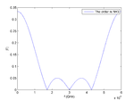
Using the design procedure outlined in Microwave Engineering (David M Pozar) pages 256-261 I wrote some Matlab code and did a plot of the magnitude of the reflection coefficient vs frequency (see chebyshev_matlab_plot.png). The matlab results matched the plots in Pozar.
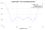
When I went on to model the system in AWR microwave office the reflection coefficient plot I obtained did not meet the specifications, the entire pass band section lies above 0.1 (see chebyshev_awr_plot.png).
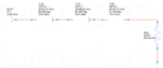
I have attached the awr project and the circuit diagram. I would greatly appreciate any help.
\[
f0:~~3*10^9 GHz\\
\Gamma_m:~~ 0.05\\
Z_{load}:~~ 100\Omega\\
Z_{line}:~~50\Omega\]
Using the design procedure outlined in Microwave Engineering (David M Pozar) pages 256-261 I wrote some Matlab code and did a plot of the magnitude of the reflection coefficient vs frequency (see chebyshev_matlab_plot.png). The matlab results matched the plots in Pozar.
When I went on to model the system in AWR microwave office the reflection coefficient plot I obtained did not meet the specifications, the entire pass band section lies above 0.1 (see chebyshev_awr_plot.png).
I have attached the awr project and the circuit diagram. I would greatly appreciate any help.